
Vivolink VL120007
Vivolink HDBaseT VL120007 70m 4K HDMI Extender Kit User Manual
Modelo: VL120007
1. Introdución
This user manual provides detailed instructions for the installation, operation, and maintenance of the Vivolink HDBaseT VL120007 70m 4K HDMI Extender Kit. This kit is designed to extend 4K HDMI signals up to 70 meters over a single Cat5e/6 cable, supporting bi-directional IR and CEC.
The Vivolink VL120007 is a premium quality product, ensuring reliable and high-performance signal transmission for various professional and home theater applications.
2. Produto rematadoview
The Vivolink VL120007 kit consists of a Transmitter unit and a Receiver unit. Both units are compact and designed for easy integration into existing setups.
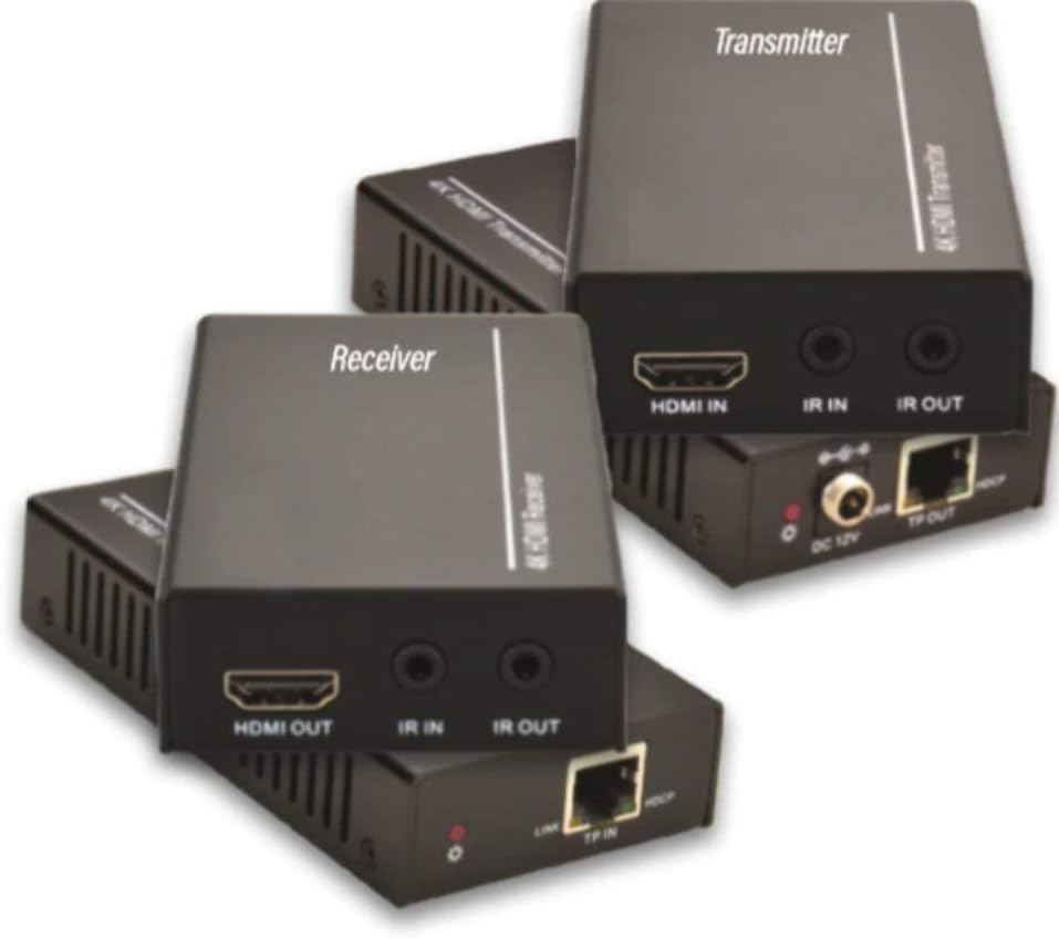
Figure 2.1: Vivolink HDBaseT VL120007 Transmitter (top) and Receiver (bottom) units. The Transmitter unit features HDMI IN, IR IN, IR OUT, DC 12V power input, and TP-OUT (HDBaseT) ports. The Receiver unit features HDMI OUT, IR IN, IR OUT, and TP-IN (HDBaseT) ports.
2.1. Características clave
- Extends 4K HDMI signals up to 70 meters (230 feet) over a single Cat5e/6 cable.
- Supports HDMI 1.4 and HDCP 2.2 compliant.
- Bi-directional IR pass-through for controlling source or display devices.
- Supports CEC (Consumer Electronics Control) functionality.
- Compact design for easy installation.
- Includes one Power Supply Unit (PSU).
3. Contido do paquete
Please verify that all items are present and in good condition upon opening the package. If any items are missing or damaged, please contact your vendor.
- 1x Vivolink HDBaseT Transmitter Unit (VL120007-TX)
- 1x Vivolink HDBaseT Receiver Unit (VL120007-RX)
- 1x 12V DC Power Supply Unit
- 1 cable IR Blaster
- 1x cable receptor IR
- 1x Manual de usuario (este documento)
4. Configuración e instalación
Before beginning installation, ensure all devices are powered off and disconnected from their power sources.
4.1. Diagrama de conexión
The following diagram illustrates a typical connection setup for the Vivolink VL120007 extender kit.
(A detailed connection diagram would typically be placed here. For illustration, imagine a diagram showing Source -> Transmitter -> Cat Cable -> Receiver -> Display.)
4.2. Pasos da instalación
- Conecta un cable HDMI desde o dispositivo fonte (por exemplo, reprodutor de Blu-ray, transmisor multimedia) ao ENTRADA HDMI porto no Transmisor unidade.
- Connect a single Cat5e/6 cable (recommended Cat6 for optimal performance) from the TP-OUT porto no Transmisor unidade ao TP-IN porto no Receptor unit. Ensure the cable is properly terminated with RJ45 connectors following TIA/EIA-568B wiring standards.
- Conecte un cable HDMI desde o SAÍDA HDMI porto no Receptor unit to your display device (e.g., TV, projector).
- For IR control, connect the IR Blaster cable to the IR OUT port on the unit that will send the IR signal (e.g., Transmitter for controlling source, Receiver for controlling display). Position the IR emitter head directly over the IR sensor of the device to be controlled.
- Conecte o cable do receptor IR ao IR IN port on the unit that will receive the IR signal. Position the IR receiver head in a location where it can receive signals from your remote control.
- Connect the included 12V DC Power Supply Unit to the DC 12 V port on either the Transmitter or Receiver unit. The system supports Power over Cable (PoC), meaning only one power supply is needed for both units.
- Power on all connected devices (source, display, and extender units).
5. Instrucións de funcionamento
Once all connections are made and power is supplied, the Vivolink VL120007 extender kit should automatically establish a connection and transmit the HDMI signal.
5.1. Indicadores LED
Both the Transmitter and Receiver units feature LED indicators to show their status:
- LED de alimentación: Illuminates when the unit is receiving power.
- LED de ligazón: Illuminates when a stable HDBaseT link is established between the Transmitter and Receiver units.
- LED de datos: May flash to indicate active HDMI data transmission.
5.2. Control IR
The bi-directional IR pass-through allows you to control your source device from the display location or your display device from the source location. Ensure the IR Blaster and IR Receiver cables are correctly positioned.
5.3. Funcionalidade da CEC
The extender kit supports CEC (Consumer Electronics Control), allowing compatible devices to communicate and control each other over the HDMI connection. This feature typically works automatically if supported by your source and display devices.
6. Mantemento
The Vivolink VL120007 extender kit requires minimal maintenance.
- Garde as unidades nun lugar fresco e seco, lonxe da luz solar directa, de fontes de calor e de humidade excesiva.
- Limpar as unidades cun pano suave e seco. Non empregar produtos de limpeza líquidos nin en aerosol.
- Asegúrese de ventilar axeitadamente arredor das unidades para evitar o sobrequecemento.
- Comprobe regularmente as conexións dos cables para asegurarse de que estean ben fixadas.
7 Solución de problemas
If you encounter issues with your Vivolink VL120007 extender kit, please refer to the following common troubleshooting steps:
| Problema | Causa posible | Solución |
|---|---|---|
| No video/audio output. |
|
|
| IR control not working. |
|
|
| Sinal intermitente ou parpadeo. |
|
|
If the problem persists after trying these steps, please contact Vivolink customer support for further assistance.
8. Especificacións
| Característica | Detalle |
|---|---|
| Número de modelo | VL120007 |
| Marca | Vivolink |
| Conformidade HDMI | HDMI 1.4 |
| Conformidade HDCP | HDCP 2.2 |
| Soporte de resolución máxima | 4K (UHD) |
| Distancia de transmisión | Up to 70 meters (230 feet) for 4K over Cat5e/6 |
| Requisito de cable | Single Cat5e/6/7 cable |
| Transmisión IR | Bidireccional |
| Soporte CEC | Si |
| Fonte de alimentación | 12V DC (PoC supported) |
| Peso do elemento | 1.21 quilogramos (aprox. 2.67 libras) |
| Fabricante | Vivolink |
9. Información da garantía
Specific warranty details are not provided in the product information. Please refer to the warranty card included with your product or contact your point of purchase for detailed warranty terms and conditions.
10. Atención ao cliente
For technical support, troubleshooting assistance beyond this manual, or warranty inquiries, please contact Vivolink customer support or your authorized dealer.
Please have your model number (VL120007) and purchase information ready when contacting support.
Ask a question about this manual
Ask about setup, troubleshooting, compatibility, parts, safety, or missing instructions. Manuals+ will review the question and use this page’s manual context to help answer it.