
1. Introdución
This manual provides essential information for the safe and efficient operation of your HKS 2.2KW (3HP) 220V Variable Frequency Drive (VFD). This device is designed to control the speed of three-phase AC motors, commonly used in applications such as CNC routers, spindle motors, grinders, mixers, conveyors, treadmills, centrifugals, elevators, lathes, and extruders. Please read this manual thoroughly before installation and operation.
Key features of this VFD include:
- Intuitive Display and Buttons: The VFD features a user-friendly display and control buttons for quick setup and operation. The control panel can be detached for remote control applications.
- Protección integral: Equipped with multiple protection mechanisms including overload, fuse, overvoltage, subvoltage, restart, stall, short circuit, and overheat protection.
- Funcionamento baixo ruído: Advanced PWM control technology and optimized component design contribute to reduced noise and electromagnetic interference, enhancing product longevity.
- Entrada/Saída versátil: Supports single-phase or three-phase 220V input and provides three-phase 0-400Hz output.
2. Información de seguridade
AVISO: Improper installation or operation can result in serious injury or death. Always follow safety precautions.
- Asegúrese de desconectar toda a alimentación antes da instalación, o cableado ou o mantemento.
- Só persoal cualificado debe instalar e realizar o mantemento deste equipo.
- Comprobar o voltage matches the VFD's specifications (AC 220V, 180-250V).
- Do not connect the VFD output to a single-phase motor directly. This VFD is designed for three-phase motors.
- Asegúrese de que o variador de frecuencia e o motor estean axeitadamente conectados á terra.
- Avoid touching internal components immediately after power-off, as residual voltage pode estar presente.
- Do not operate the VFD with damaged cables or if the casing está aberto.
- External resistance is not supported. Adjust parameters for similar functionality.
- For heavy-duty motors, consider a higher power VFD.
- Delta (Δ) connection is recommended for the motor.
3. Produto rematadoview
The HKS VFD-2200 is a compact and robust variable frequency drive. It features a digital display and a control panel for easy interaction.

Figura 3.1: Fronte view of the HKS VFD-2200. This image shows the main unit with its digital display, control buttons, and adjustment knob.
3.1 Panel de control e pantalla
The VFD's control panel provides visual feedback and allows for parameter adjustments. It can be detached for remote operation.

Figura 3.2: The detachable control panel of the VFD. This feature allows for flexible installation and remote control capabilities.

Figura 3.3: Detallado view of the control panel buttons and their functions. This includes RUN/STOP, SET, JOG, REV/FWD, and the adjustment knob, along with indicators for ERROR, FWD, REV, ANALOG, SEGMENT, and PANEL.
| Botón | Descrición |
|---|---|
| CORRER / PARAR | Starts the inverter when idle, stops the inverter when running. |
| PARAR / RESETAR | Stops the inverter if running; resets the inverter if a fault occurs; returns to the parent menu when navigating menus. |
| REV / FWD | Changes the inverter's direction (clockwise/counter-clockwise rotation). Operates during runtime. |
| SET | Enters the menu setting. In the sub-menu, saves the parameter and moves to the next item. |
| ▲ / ▼ | Menu item selection and sub-item data modification. |
| ◀ / ▶ | Menu item content modification selection or inverter jogging button. |
| Botón de axuste | Controls the output frequency. |
| Indicador | Descrición |
|---|---|
| ERRO | Indicador de avaría. |
| FWD | Indicador de rotación no sentido horario. |
| REV | Anti-clockwise rotation indicator. |
| ANALÓXICO | Indicador de frecuencia de entrada analóxica. |
| SEGMENTO | Indicador de frecuencia de entrada de segmento. |
| PANEL | Indicador de frecuencia de entrada do panel. |
| LCD dixital | Inverter runtime frequency. If inverter stops, it flashes. The display data is given by "Pn01" data. |
4. Especificacións
| Parámetro | Valor |
|---|---|
| Número de modelo | VFD-2200 |
| Poder | 2.2 KW (3 HP) |
| Vol. De entradatage | AC 220V (180-250V) |
| Vol. De saídatage | 220 V |
| Corrente de entrada | 10A |
| Corrente de saída | 15A |
| Frecuencia de entrada | 40-60 Hz |
| Frecuencia de saída | 0-400 Hz |
| Fase de entrada | Single-phase or Three-phase |
| Fase de saída | Trifásico |
| Peso do elemento | 2.35 libras |
| Dimensións do paquete | 7.48 x 7.24 x 5.43 polgadas |

Figura 4.1: Physical dimensions of the HKS VFD-2200, showing approximate measurements of 5.5 inches in height, 4.4 inches in width, and 3.3 inches in depth.
5. Configuración e cableado
Proper wiring is critical for the safe and correct operation of the VFD. Ensure all power is off before proceeding.
5.1 Diagrama de conexión básico
The VFD supports both single-phase and three-phase 220V input. The output is always three-phase for motor control.

Figura 5.1: Simplified wiring diagram showing the connection from a circuit breaker to the VFD (R, S, T terminals) and then from the VFD (U, V, W terminals) to a three-phase motor. This illustrates a typical setup for connecting the VFD to power and a motor.

Figura 5.2: Detailed basic connection diagram for the HKS VFD. This schematic shows connections for single-phase 220V (R, T) or three-phase 220V (R, S, T) input, and three-phase output (U, V, W) to the motor. It also illustrates control terminals for FWD/STOP, REV/STOP, RESET, multi-speed inputs, digital frequency up/down, and external analog signal input (0-5V, 0-10V, 0-20mA) for frequency control via an external potentiometer.
- Input Power (R, S, T): Connect your 220V AC power supply. For single-phase input, connect to R and T terminals. For three-phase input, connect to R, S, and T terminals.
- Saída do motor (U, V, W): Connect these terminals to your three-phase motor. Ensure the motor is rated for 220V three-phase operation.
- Conexión a terra: Always connect the ground terminal of the VFD to a reliable earth ground.
- Terminais de control: The VFD provides various control terminals for external start/stop, reverse, reset, multi-speed settings, and analog input for frequency control (e.g., with an external potentiometer). Refer to the detailed wiring diagram (Figure 5.2) for specific connections.
5.2 Configuración inicial dos parámetros
After wiring, it is essential to configure basic parameters. Consult the full parameter list in the comprehensive manual for detailed settings. Common initial settings include:
- PN02: Set maximum output frequency (e.g., 50Hz or 60Hz depending on region).
- PN10: Set motor rated frequency.
- PN12: Set motor rated voltage.
- PN08 & PN09: Adjust acceleration and deceleration times. Default is 10 seconds.
If using an external potentiometer for frequency control, ensure the corresponding analog input parameters are correctly configured.
6. Instrucións de funcionamento
Once the VFD is correctly wired and initial parameters are set, you can begin operation.
6.1 Funcionamento básico
- Encendido: Apply power to the VFD. The digital display will illuminate.
- Establecer frecuencia: Use the adjustment knob on the control panel to set the desired output frequency. Alternatively, use the ▲/▼ buttons or an external analog input if configured.
- Arranque do motor: Preme o CORRER button. The FWD or REV indicator will light up, and the motor will start accelerating to the set frequency.
- Cambiar dirección: Preme o REV / FWD button during operation to change the motor's rotation direction.
- Parada do motor: Preme o PARAR / RESETAR button. The motor will decelerate and stop.
6.2 Operación avanzada
The VFD supports various advanced functions accessible through parameter settings. These include multi-speed operation, PID control, and more. Refer to the detailed parameter manual for specific configurations.
7. Mantemento
Un mantemento regular garante a lonxevidade e o funcionamento fiable do seu variador de frecuencia.
- Limpeza: Periodically clean the VFD's exterior and cooling vents to prevent dust accumulation, which can hinder heat dissipation. Use a soft, dry cloth. Do not use liquid cleaners.
- Refrixeración: Ensure adequate airflow around the VFD. The design incorporates multiple holes and sufficient space between components for effective cooling.
- Conexións: Periodically check all wiring connections for tightness and signs of corrosion or damage. Loose connections can lead to poor performance or faults.
- Condicións ambientais: Operate the VFD within its specified environmental limits (temperature, humidity, vibration).

Figura 7.1: Illustration of the VFD's cooling system, showing the internal fan and airflow paths designed to maintain optimal operating temperatures and ensure low noise operation.
8 Solución de problemas
This section addresses common issues and their potential solutions. The VFD is equipped with various protection features that may trigger an error state.
8.1 Fallos comúns e solucións
- Protección contra sobrecarga: If the motor draws excessive current, the VFD will trip. Check the motor load, ensure the motor is not jammed, and verify VFD power rating matches the motor.
- Sobrevoltage Protection (DC voltage > 400V): Occurs if the input voltage is too high or during rapid deceleration of a high-inertia load. Check input voltage and consider increasing deceleration time (PN09).
- Baixo Voltage Protection (DC voltage < 200V): Occurs if the input voltage drops below the acceptable range. Check input power supply.
- Protección contra curtocircuítos: Indicates a short circuit in the motor or output wiring. Disconnect power and inspect motor and wiring for damage.
- Protección contra sobrecalentamento: The VFD's internal temperature is too high. Check for blocked cooling vents, ensure proper ambient temperature, and verify the cooling fan is operational.
- Protección de bloqueo: The motor is unable to rotate or is heavily loaded. Reduce load or check for mechanical issues with the motor.
- Instantaneous Start / Overcurrent Error with External Switch: Some users have reported that when the VFD is set for start/stop by an external switch, the acceleration time parameter (PN08) may be ignored, leading to an instantaneous start and potential overcurrent errors. If this occurs, verify parameter settings and consider using panel control or consulting technical support for advanced configurations.
If a fault occurs, the ERROR indicator will illuminate. Press the PARAR / RESETAR button to clear the fault after addressing the underlying issue.
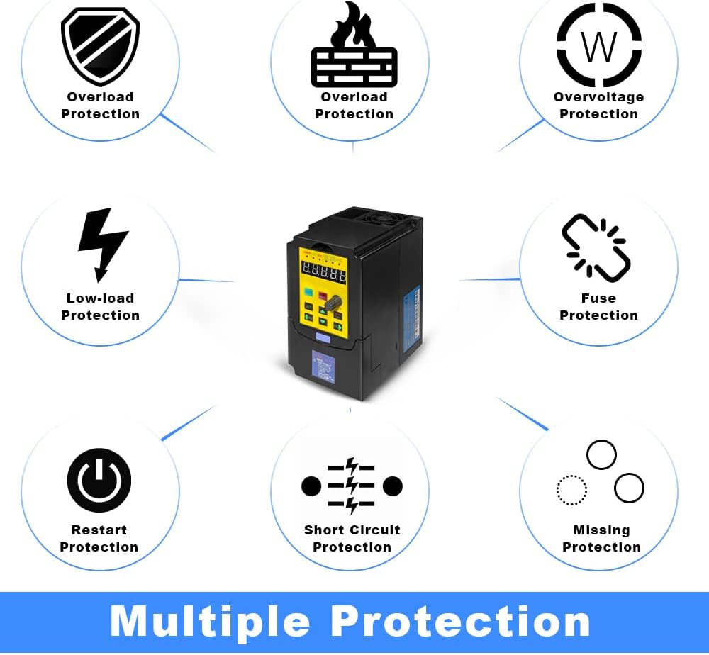
Figura 8.1: Diagram illustrating the various protection features of the HKS VFD, including overload, overvoltage, low-load, fuse, restart, stall, short circuit, and overheat protection.
9. Garantía e soporte
For warranty information and technical support, please contact the seller or manufacturer directly. It is recommended to provide details of your setup, including pictures of the load equipment parameters (e.g., motor nameplate), when seeking assistance.
Optional protection plans may be available for extended coverage. Please refer to your purchase documentation for details.