1. Introdución
This manual provides detailed instructions for the installation, operation, and maintenance of the PowMr 30A PWM Solar Charge Controller. This device is designed to manage the power flow from your solar panels to your battery bank, ensuring efficient charging and protecting your batteries from overcharge and over-discharge. It is compatible with 12V, 24V, 36V, and 48V systems and various battery types, including AGM, Gel, Flooded, and Lithium.
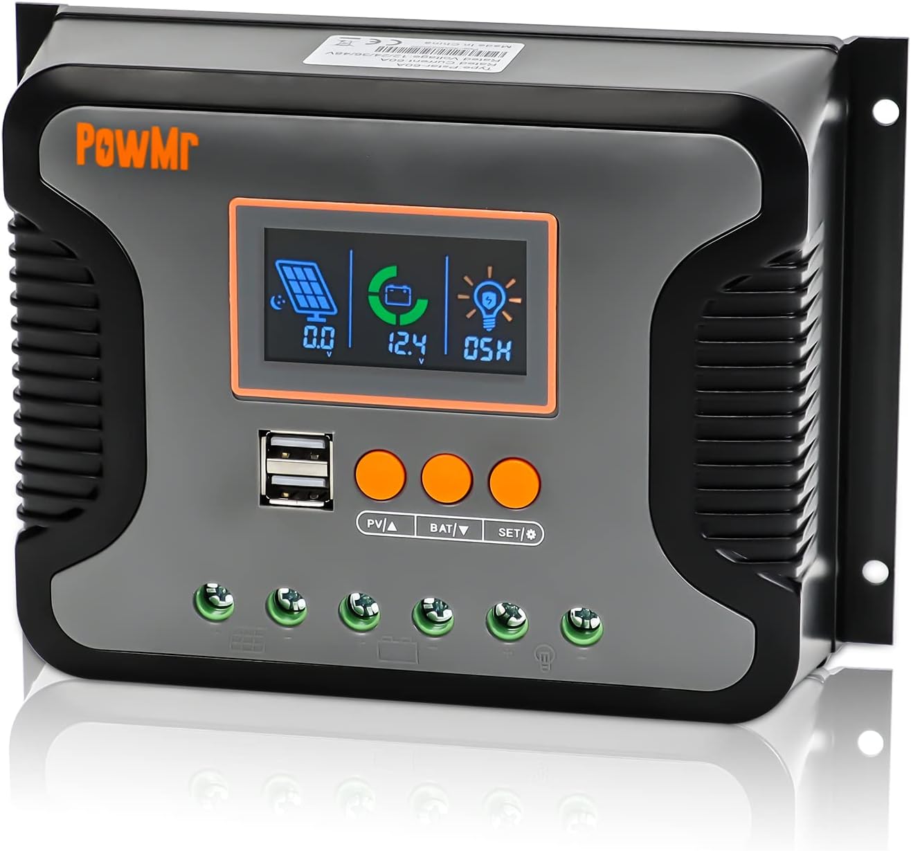
Figura 1: Fronte view of the PowMr 30A PWM Solar Charge Controller, showing the LCD display, USB ports, and control buttons.
2. Características clave
- Vol. do sistema automáticotage Detección: Automatically detects 12V, 24V, 36V, and 48V DC systems.
- Wide PV Input VoltagRango: Supports a maximum PV input voltage de 100 V CC.
- Ampla compatibilidade de baterías: Compatible with AGM, Gel, Flooded, LiFePO4, and Ternary Lithium batteries, with user-defined battery settings.
- 3-StagCarga PWM: Utilizes Bulk, Boost, and Float charging stages for optimized battery health and longevity.
- Integrated Dual USB Ports: Provides 5V/2.5A (max) output for charging mobile devices.
- Pantalla LCD retroiluminada: Real-time monitoring of charging current, generated energy, temperature, battery voltage, e códigos de erro.
- Adjustable Load Enable Duration: Configurable solar light control and time control for load output.
- Proteccións completas: Includes protection against overheating, output short circuit, over-discharging, reverse polarity connection, and maximum charging current limits.
- Refrixeración por convección natural: Fanless design for silent operation and efficient heat dissipation.

Figura 2: Máisview of the multiple safety protections integrated into the controller.
3. Configuración e instalación
Before installation, please read all safety instructions carefully. Ensure all connections are secure and correct to prevent damage to the controller or other components.
3.1 Precaucións de seguridade
- Always connect the battery first, then the solar panel, and finally the load.
- Disconnect in the reverse order: load, then solar panel, then battery.
- Asegúrese de que haxa unha ventilación axeitada arredor do controlador.
- Install in a dry, cool environment, away from direct sunlight and moisture.
- Empregar disyuntores e fusibles axeitados para todas as conexións.
3.2 Diagrama de cableado
Follow the wiring sequence below to ensure safe and proper operation. Incorrect wiring may damage the controller.

Figure 3: Connection diagram for the PowMr Solar Charge Controller, showing connections for solar panels, battery, and load.
3.3 Pasos de conexión
- Conecte a batería: Connect the positive and negative terminals of the battery to the corresponding battery terminals on the controller. The controller will automatically detect the system voltage (12 V/24 V/36 V/48 V).
- Conecta os paneis solares: Connect the positive and negative terminals of the solar panels to the corresponding PV input terminals on the controller. Ensure the PV open circuit voltage does not exceed 100V DC.
- Conectar a carga: Connect the positive and negative terminals of your DC load to the corresponding load terminals on the controller.
Important: Always connect the battery first and disconnect it last. This sequence prevents potential damage from voltage picos.
4. Instrucións de funcionamento
The PowMr solar charge controller features an intuitive LCD display and three function keys for easy monitoring and parameter configuration.
4.1 LCD Screen Display and Buttons
The LCD screen provides real-time data and allows for parameter adjustments. The three buttons are: PV▲ (Up), BAT▼ (Down), and SET/Ⓞ (Set/Enter).

Figure 4: LCD screen display and button functions for navigation and settings.
Checking Information:
- Press "PV▲" to switch PV information (PV input voltage, PV input current, PV input power).
- Press "BAT▼" to switch battery information (current battery voltage, temperatura do equipo, calibración da batería voltage, tipo de batería, aumento de volumen de cargatage, carga flotante voltage, baixo volume de recuperación de corte de CCtage, vol. de corte de CC baixotage).
4.2 Selección do tipo de batería
O controlador admite varios tipos de baterías. É fundamental seleccionar o tipo de batería correcto para unha carga e unha duración óptimas da batería.

Figure 5: Battery type compatibility and selection options.
To select the battery type:
- Press "BAT▼" until the battery type icon is displayed.
- Press and hold "SET/Ⓞ" to enter the setting mode.
- Use "PV▲" or "BAT▼" to cycle through the available battery types (e.g., SEL, USE, FLD, GEL, LiFePO4, Ternary Lithium, User-defined).
- Press "SET/Ⓞ" to confirm your selection.
4.3 Batería Voltage Calibración
For precise battery voltage readings, you can calibrate the controller's voltage measurement against a multimeter.

Figura 6: Volume da bateríatage. proceso de calibración.
Para calibrar:
- Navega ata o "volume de calibración da batería"tage" item using "BAT▼".
- Press and hold "BAT▼" to enter the calibration setting.
- Measure the actual battery voltage with a precise multimeter.
- Use "PV▲" or "BAT▼" to adjust the displayed voltage on the controller to match the multimeter reading.
- Press "SET/Ⓞ" to confirm and save the calibration.
4.4 3-Stage PWM Charging
O controlador emprega un sistema de 3 segundostage charging algorithm to optimize battery charging and extend battery life.

Figure 7: Explanation of the 3-stage PWM charging process.
- Carga masiva: The battery is charged at maximum current until the voltage alcanza o volume de carga impulsiva configuradotage.
- Aumentar a carga: The battery continues to charge at the configured boost charging voltage until it reaches a full charge state, with the charge current gradually decreasing.
- Carga flotante: The controller reduces the battery voltage by lowering the charging current, maintaining the battery at a floating charging voltage to keep it fully charged.
4.5 Configure Load Enable Duration
The load output can be configured for continuous operation or controlled by solar light and time settings.
To configure load duration:
- Press and hold "SET/Ⓞ" to enter the load mode setting.
- Use "PV▲" or "BAT▼" to select the desired mode:
- -00H: Solar light control mode (load enabled when solar energy is sufficient).
- -24H: Turn on load immediately (default, continuous output).
- -01H-23H: Adjust the load enable duration (e.g., 01H for 1 hour, 23H for 23 hours).
- Press "SET/Ⓞ" to confirm your selection.
5. Mantemento
Un mantemento regular garante a lonxevidade e o rendemento óptimo do seu controlador de carga solar.
- Limpeza: Manteña o controlador limpo e libre de po e residuos. Use un pano seco para limpar.
- Conexións: Periodically check all wiring connections to ensure they are tight and free from corrosion. Loose connections can cause overheating and poor performance.
- Ventilación: Ensure the area around the controller is well-ventilated to allow for proper heat dissipation. Do not block the heat sink fins.
- Condicións ambientais: Verifique que o ambiente de funcionamento se manteña dentro dos rangos de temperatura e humidade especificados.
- Saúde da batería: Monitorea o estado e o volume da túa bateríatage regularly. Ensure the battery type setting on the controller matches your battery.
6 Solución de problemas
Esta sección aborda problemas comúns que podes atopar co teu controlador de carga solar.
| Problema | Causa posible | Solución |
|---|---|---|
| O controlador non se acende / Non hai pantalla | Batería non conectada ou de baixo volumetage) polaridade inversa. | Comprobe as conexións da batería e o voltage. Ensure correct polarity. Charge battery if voltage é demasiado baixo. |
| A batería non se está cargando | Solar panels not connected; insufficient sunlight; PV input voltage too low/high; incorrect battery type setting. | Check solar panel connections. Ensure adequate sunlight. Verify PV voltage is within range. Confirm correct battery type setting. |
| A carga non funciona | Load disconnected; battery low voltage protection; load overcurrent/short circuit; load control setting. | Check load connections. Check battery voltage. Reduce load or clear short circuit. Adjust load enable duration setting. |
| Sobrequecemento | Poor ventilation; excessive load/charging current. | Ensure proper airflow around the controller. Reduce load or check for short circuits. |
| Vol. imprecisotage lectura | Calibration needed; loose battery connections. | Perform battery voltage calibration (refer to Section 4.3). Check and tighten battery connections. |
7. Especificacións
Detailed technical specifications for the PowMr 30A PWM Solar Charge Controller.

Figure 8: Physical dimensions of the PowMr 30A PWM Solar Charge Controller.
| Parámetro | Valor |
|---|---|
| Número de modelo | 30A |
| Sistema Voltage | 12V/24V/36V/48V Automático |
| Vol. de entrada PV máxtage | 100V DC |
| Max. Input Power (12V System) | 360 W |
| Max. Input Power (24V System) | 720 W |
| Max. Input Power (36V System) | 1080 W |
| Max. Input Power (48V System) | 1440 W |
| Tipo de porto de carga | Dual USB (5V/2.5A max) |
| Dimensións do produto | 7.36 x 3.7 x 1.93 polgadas |
| Peso do elemento | 1.12 libras |
| Tipo de visualización | LCD |
| Fabricante | Pow Sr |
8. Información de seguridade
The PowMr solar charge controller is equipped with multiple protection features to ensure safe operation of your solar power system.
- Protección de conexión contra polaridade inversa: Evita danos se as conexións da batería ou do panel solar están invertidas.
- Protección contra sobredescarga: Automatically disconnects the load when battery voltage drops below a safe level to prevent deep discharge.
- Protección contra sobrecalentamento: The controller will reduce charging current or shut down if its internal temperature exceeds safe limits.
- Protección contra curtocircuítos de saída: Protects the controller and load from damage in case of a short circuit on the load terminals.
- Maximum Charging Current Limitation: Limits the current to prevent overcharging the battery.
Always adhere to local electrical codes and safety standards during installation and operation. If you are unsure about any aspect of installation, consult a qualified electrician or solar professional.
9. Garantía e soporte
For warranty information and technical support, please refer to the documentation included with your purchase or visit the official PowMr websitio. Garde o recibo da compra como xustificante de compra para reclamacións de garantía.
No relevant product videos were found for this model.