
1. Introdución
This manual provides detailed instructions for the installation, operation, and maintenance of your OLONETO 100A Solar Charge Controller. This device is designed to manage power flow from your solar panel to your battery bank and DC loads, ensuring efficient charging and protection for your battery system. It supports 12V, 24V, 36V, and 48V battery systems with automatic voltage identificación.
Note: This controller utilizes a combination of MPPT and PWM charging technologies. It is not a 100% true MPPT controller.
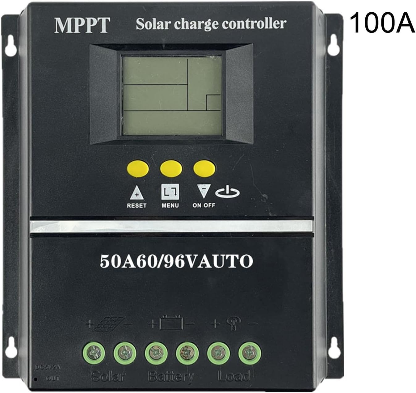
Figura 1: Fronte view of the OLONETO 100A Solar Charge Controller, showing the LCD display, control buttons, and connection terminals. The "100A" rating is visible on the top right.
2. Instrucións de seguridade
- Ensure all connections are tight and correct to prevent damage to the controller or other components.
- Conecta sempre a batería ao controlador primeiro, and then connect the solar panel. Disconnect in the reverse order: solar panel first, then battery. Failure to follow this sequence may damage the controller.
- Asegúrese de que a batería voltage is sufficient for the controller to recognize the system voltage (e.g., >10V for 12V battery, >20V for 24V battery, >30V for 36V battery, >40V for 48V battery).
- Instale o controlador nunha zona ben ventilada, lonxe da luz solar directa, de altas temperaturas e da humidade.
- Do not attempt to repair or modify the controller yourself. Contact qualified personnel for service.
3. Características do produto
The OLONETO Solar Charge Controller offers several key features for efficient solar power management:
- Vol. Automáticotage Identificación: Automatically detects 12V, 24V, 36V, or 48V battery systems.
- Pantalla LCD: Provides real-time information on battery status, charging parameters, and load status.
- Saída USB dual: Convenient 5V output for charging mobile phones and other USB devices.
- Parámetros axustables: Allows users to customize charging and discharge settings.
- Smart Charge Management: Optimizes battery charging to prolong battery life.
- Protección ambiental: Designed with green environmental protection principles.
- Automatic Focusing MPPT Tracking: High charging efficiency with non-stop detection during charging and bidirectional focusing tracking.

Figure 2: Diagram illustrating key features of the solar charge controller, including LCD display for battery power supply voltage, smart charge capabilities, 5V USB output, adjustable parameters, and green environmental protection.

Figure 3: Image highlighting the automatic focusing MPPT tracking feature, which ensures high charging efficiency and continuous detection during the charging process.
4. Configuración e instalación
4.1 Secuencia de cableado
- Conecte a batería: Connect the battery to the controller's battery terminals. Ensure correct polarity (+ to + and - to -). The controller will automatically detect the battery voltage.
- Conecta o panel solar: Connect the solar panel to the controller's solar panel terminals. Ensure correct polarity.
- Conectar a carga de CC (opcional): Connect your DC loads to the controller's load terminals. Ensure correct polarity.
Important: Always follow this connection order: Battery → Solar Panel → Load. To disconnect, follow the reverse order: Load → Solar Panel → Battery.
4.2 Recommended Solar Panel Voltage
- Para 12 V battery systems: Use a solar panel with approximately 18 V saída.
- Para 24 V battery systems: Use a solar panel with approximately 30-37 V saída.
- Para 36 V battery systems: Use a solar panel with approximately 45-55 V saída.
- Para 48 V battery systems: Use a solar panel with approximately 60-72 V saída.
4.3 Esquemas de cableado

Figure 4: Basic wiring diagram showing connections for the solar panel, battery, and DC loads to the controller. Ensure positive (+) and negative (-) terminals are correctly matched.

Figure 5: Detailed wiring diagram illustrating connections for the solar panel, battery, DC load, and the integrated USB output for charging external devices.
5. Instrucións de funcionamento
5.1 Initial Power-Up and Display
Once the battery is connected, the controller's LCD display will power on, showing current system parameters. The controller automatically identifies the battery voltage (12 V, 24 V, 36 V ou 48 V).
5.2 Funcións dos botóns
- ▲ (Up/Reset): Used to increase values during setting, or as a reset function.
- MENÚ: Used to navigate through display screens and enter/exit setting modes.
- ▼ (Down/On/Off): Used to decrease values during setting, or to toggle the DC load on/off.
5.3 Vol. de cargatage Configuración
To adjust charging parameters:
- After connecting the battery, ensure the clock is set and saved (see 5.4 Clock Setting).
- Manteña prema a tecla "▲" button for 3-5 seconds. The screen will display "L**V" (floating charging voltage).
- Usa a opción "▼" button to adjust the floating charging voltage.
- Briefly press "▲" again. The screen will display "H**V" (boost charging voltage).
- Usa a opción "▼" button to adjust the boost charging voltage.
- Briefly press "▲" again. The screen will display "F**V" (low-voltage corte de voltage for DC load).
- Usa a opción "▼" button to adjust the low-voltage corte de voltage.
- After making all desired adjustments, press and hold the "▲" button for 3-5 seconds to save the settings and exit.
5.4 Configuración do reloxo
To set the internal clock:
- Asegúrese de que a batería estea conectada.
- Prema a tecla "▲" ou "▼" buttons to navigate to the clock setting interface.
- Usa a opción "▲" e "▼" buttons to adjust the time.
- Briefly press the "MENU" button (represented as "□" in some descriptions) to save the clock setting.
5.5 Load Protection Voltage Referencia
The following are typical battery charging voltages for different system voltages:
- Cando se utiliza a 12 V battery, the battery charging voltage is typically 13.7 V.
- Cando se utiliza a 24 V battery, the battery charging voltage is typically 27.4 V.
- Cando se utiliza a 36 V battery, the battery charging voltage is typically 41.1 V.
- Cando se utiliza a 48 V battery, the battery charging voltage is typically 54.8 V.
6. Mantemento
- Inspección periódica: Comprobe periodicamente todas as conexións do cableado para comprobar se están ben apertadas e se presentan corrosión.
- Limpeza: Manteña o controlador limpo e libre de po e residuos. Use un pano seco para limpar.
- Ventilación: Asegúrate de que a zona de instalación permaneza ben ventilada para evitar o sobrequecemento.
- Saúde da batería: Monitorea o estado e o volume da túa bateríatage regularly to ensure optimal system performance.
7 Solución de problemas
| Problema | Causa posible | Solución |
|---|---|---|
| A pantalla do controlador está desactivada. | Non hai batería conectada ou o volume da bateríatage moi baixo. | Connect battery or ensure battery voltage is above minimum threshold (e.g., >10V for 12V system). |
| Sen carga desde o panel solar. | Solar panel not connected, incorrect polarity, or insufficient sunlight. | Check solar panel connections and polarity. Ensure adequate sunlight. |
| Voltage identification error. | Batería voltage was too low when connected initially. | Asegúrese de que a batería voltage is above the minimum threshold before connecting to the controller. Disconnect and reconnect the battery. |
| DC load not working. | Load is off, incorrect wiring, or battery voltage is below low-voltage corte. | Check load connection and polarity. Press the "▼" button to toggle load. Check battery voltage and adjust low-voltage cut-off if necessary. |
8. Especificacións
| Parámetro | Valor |
|---|---|
| Modelo | 100A |
| Marca | OLONETO |
| Sistema Voltage | 12V/24V/36V/48V Automático |
| Tecnoloxía de carga | MPPT/PWM Hybrid |
| Saída USB | Dual USB, 5V |
| Peso do elemento | 200 gramos |
| Dimensións (aprox.) | 190 mm (7.48 polgadas) x 180 mm (7.08 polgadas) |

Figure 6: Physical dimensions of the solar charge controller, showing approximate measurements of 190mm (7.48 inches) in width and 180mm (7.08 inches) in height.
9. Garantía e soporte
Para obter información sobre a garantía e asistencia técnica, consulte a documentación incluída coa súa compra ou póñase en contacto co seu vendedor. Garde o comprobante de compra para calquera reclamación de garantía.