
1. Introdución
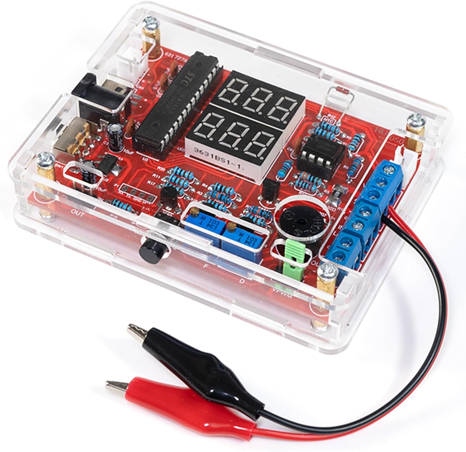
The EIELE DIY Multifunctional Meter Soldering Practice Kit (Model HYPP0143) is designed for electronics enthusiasts, students, and beginners to learn soldering skills and understand basic electronic principles. This kit allows you to assemble a fully functional meter capable of measuring various electrical parameters.
Upon successful assembly, the meter can perform the following functions:
- Voltage Medición
- Medición actual
- Medición de temperatura
- Logic Level Detection
- Circuit Continuity (On/Off) Testing
- Signal Frequency Measurement
- Medición do ciclo de traballo
- Signal Output (PWM)
This manual provides step-by-step instructions for assembly, operation, and maintenance to ensure a successful and educational experience.
2. Información de seguridade
Please read and understand all safety precautions before beginning assembly or operation. Improper use can result in injury or damage to the device.
2.1 Soldering Safety
- Ventilación: Traballa sempre nunha zona ben ventilada para evitar a inhalación de fumes de soldadura.
- Protección ocular: Wear safety glasses to protect your eyes from splashes of molten solder or flying component leads.
- Hot Iron: Soldering irons reach high temperatures. Avoid direct contact with the tip. Use a soldering iron stand.
- Risco de incendio: Keep flammable materials away from your soldering workstation.
- Soldadura sen chumbo: If using lead-free solder, note that it requires higher temperatures and may be more difficult to work with for beginners.
2.2 Seguridade eléctrica
- Fonte de alimentación: Use only a stable 5V DC power supply as specified. Incorrect voltage can damage the circuit.
- Curtocircuítos: Ensure no bare wires or component leads touch unintentionally, which could cause a short circuit.
- Capacitores: Electrolytic capacitors must be installed with correct polarity. Incorrect installation can lead to damage or explosion.
- Descarga estática: Handle electronic components with care to prevent damage from electrostatic discharge (ESD).
3. Contido do paquete
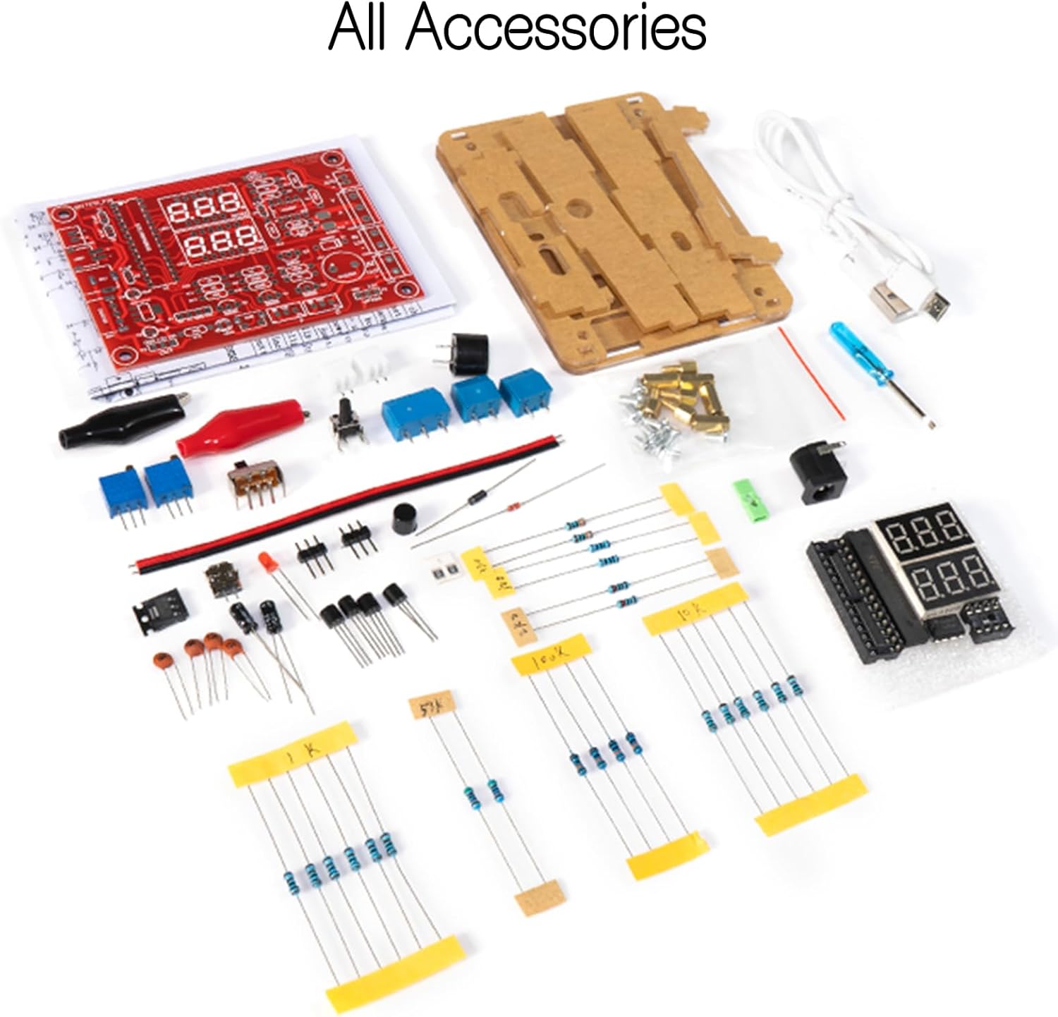
Before starting assembly, verify that all components listed below are present in your kit. Refer to Figure 3.1 for a visual representation of the kit contents.
- Placa de circuíto impreso (PCB)
- Acrylic Enclosure Panels
- Microcontroller (e.g., STC series)
- Operativo Amplifiers (e.g., LM358)
- 7-Segment LED Displays
- Resistors (various values)
- Capacitors (electrolytic and ceramic)
- Diodes (e.g., 1N4007)
- Transistores
- Potentiometers (adjustable resistors)
- Interruptor de alternancia
- Pulsadores
- Zumbador
- NTC Thermistor (for temperature measurement)
- Bloques de terminais
- Jack de alimentación DC
- Cable de alimentación USB
- Test Leads (alligator clips)
- Screws and Standoffs for enclosure
- Desaparafusador pequeno
- Instrucións en papel
4. Instrucións de montaxe
This section guides you through the assembly process. Take your time, follow each step carefully, and double-check your work.
4.1 Ferramentas necesarias (non incluídas)
- Soldador
- Solder (preferably thin gauge)
- Solder Wick or Solder Pump (for desoldering mistakes)
- Wire Cutters/Flush Cutters
- Alicates de punta de agulla
- Multimeter (optional, for testing components)
4.2 Component Identification and Preparation
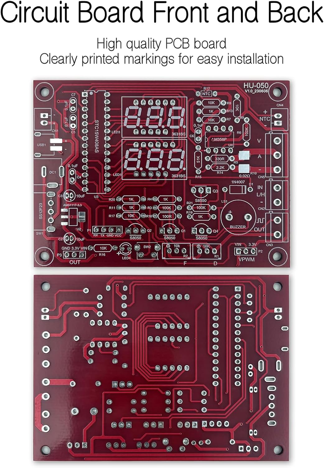
Before soldering, identify each component. Resistors are color-coded, capacitors have values printed, and diodes/LEDs have polarity markings. The PCB has silkscreen labels indicating where each component should be placed and its value.
4.3 Soldering Process
It is generally recommended to solder components from smallest to largest. This prevents larger components from obstructing access to smaller pads.
- Resistencias: Bend the leads, insert into the correct holes, and solder. Trim excess leads.
- Diodos: Pay close attention to the polarity (band on diode matches band on PCB silkscreen).
- Capacitores: Ceramic capacitors are non-polarized. Electrolytic capacitors have a stripe indicating the negative lead; match this to the PCB marking.
- IC Sockets: If included, solder the IC sockets first, ensuring the notch aligns with the PCB marking. Insert the ICs into the sockets after all soldering is complete.
- Transistors, LEDs, Buzzer: Observe polarity and orientation as indicated on the PCB.
- Switches, Buttons, Potentiometers, Terminal Blocks, DC Jack: Solder these larger components last.
- 7-Segment Displays: Solder these carefully, ensuring they are flush with the PCB.

4.4 Enclosure Assembly
Once all components are soldered and the PCB is inspected for any solder bridges or cold joints, assemble the acrylic enclosure.
- Remove the protective film from all acrylic panels.
- Mount the PCB onto the bottom acrylic panel using the provided standoffs and screws.
- Attach the side panels, ensuring all cutouts align with the PCB components (e.g., DC jack, switches, terminal blocks).
- Secure the top panel with the remaining screws.
5. Instrucións de funcionamento
This section details how to power on your multifunctional meter and utilize its various measurement capabilities.
5.1 Acendido
Connect the provided USB power cable to the DC power jack on the meter and to a 5V USB power source (e.g., phone charger, computer USB port). Flip the toggle switch to the ON position. The 7-segment displays should illuminate.
5.2 Funcións de medición
The meter offers multiple measurement modes. Use the push buttons to cycle through the modes. Refer to Figure 5.1 for connection diagrams for each function.

- Voltage e medición de corrente:
Connect the positive and negative terminals of the circuit under test to the designated 'V' and 'A' input terminals. The display will show voltage in Volts (V) and current in Amperes (A). Ensure connections are made correctly for series (current) and parallel (voltage) measurements. - Medición de temperatura:
Connect the NTC thermistor to the dedicated temperature input terminals. The display will show ambient and external temperature readings. - Logic Level Detection:
Connect the signal to be tested to the 'IN L/H' input. The display will indicate 'L' for low logic level, 'H' for high logic level, or '-' for an undefined state. - Circuit Continuity (On/Off):
Connect the test leads to the 'IN L/H' input. The display will indicate continuity (on) or open circuit (off). - Signal Frequency and Duty Cycle Measurement:
Connect the signal to be analyzed to the 'IN L/H' input. The display will show the signal's frequency in kHz and its duty cycle in percentage. - Signal Output (PWM):
The meter can generate a Pulse Width Modulation (PWM) signal from the 'PWM OUT' terminal. Use the onboard potentiometers to adjust the frequency and duty cycle of the output signal. The display will show the current frequency and duty cycle settings.
6. Especificacións
The following table outlines the key specifications of the EIELE DIY Multifunctional Meter Soldering Practice Kit.
| Característica | Especificación |
|---|---|
| Número de modelo | HYPP0143 |
| Fabricante | HYIC |
| Material | Copper (PCB), Acrylic (Enclosure) |
| Tipo de visualización | LCD (7-Segment LED Displays) |
| Entrada de enerxía | 5V DC (a través de USB) |
| Peso do elemento | 6.1 onzas (aprox. 173 g) |
| Compoñentes incluídos | KIT (unassembled components) |

7 Solución de problemas
If you encounter issues during or after assembly, consult the following troubleshooting tips:
- Sen alimentación/a pantalla non se ilumina:
Check your 5V power supply. Ensure the power cable is securely connected. Verify the toggle switch is in the ON position. Inspect the DC power jack and its solder joints for proper connection. - Incorrect Readings or Malfunction:
Review all solder joints for cold joints (dull, lumpy appearance) or solder bridges (solder connecting two adjacent pads). Check component polarity, especially for diodes, LEDs, and electrolytic capacitors. Ensure all ICs are correctly seated in their sockets (if applicable) and oriented properly. - Compoñentes que faltan:
Refer to the package contents list (Section 3) and Figure 3.1 to confirm all parts were received. - Danos físicos:
If any components or the PCB appear physically damaged, do not proceed with assembly. Contact customer support.
If the project does not work properly after soldering, please contact EIELE customer support for professional assistance. Our goal is for each user to successfully complete their project.
8. Mantemento
To ensure the longevity and proper functioning of your multifunctional meter, follow these maintenance guidelines:
- Limpeza: Use a soft, dry cloth to clean the acrylic enclosure. Avoid abrasive cleaners or solvents that could damage the plastic.
- Almacenamento: Garde o medidor nun lugar seco e sen po, lonxe da luz solar directa e de temperaturas extremas.
- Manexo: Handle the meter with care to avoid dropping it or subjecting it to physical shock, which could damage internal components or solder joints.
- Apague cando non estea en uso: Always switch off the meter and disconnect the power supply when not in use for extended periods.
9. Garantía e soporte
EIELE is committed to the quality of its products. All kit parts are rigorously tested and are high-quality components.
If you encounter any difficulties during assembly or if the completed project does not function as expected, please do not hesitate to contact EIELE customer support. We are dedicated to providing professional assistance until you are satisfied with your project's completion.
For support, please refer to the contact information provided with your purchase or on the EIELE official websitio.