
Tyenaza ETCR2100A+
Tyenaza ETCR2100A+ Digital Clamp Resistance Tester User Manual
Model: ETCR2100A+
1. Introdución
This manual provides essential instructions for the safe and effective operation of the Tyenaza ETCR2100A+ Digital Clamp Resistance Tester. This device is designed for accurate measurement of grounding resistance and circuit resistance, featuring a dustproof and shockproof structure for reliable performance in various industrial and departmental settings.
Please read this manual thoroughly before using the instrument to ensure proper handling and to prevent damage or injury.
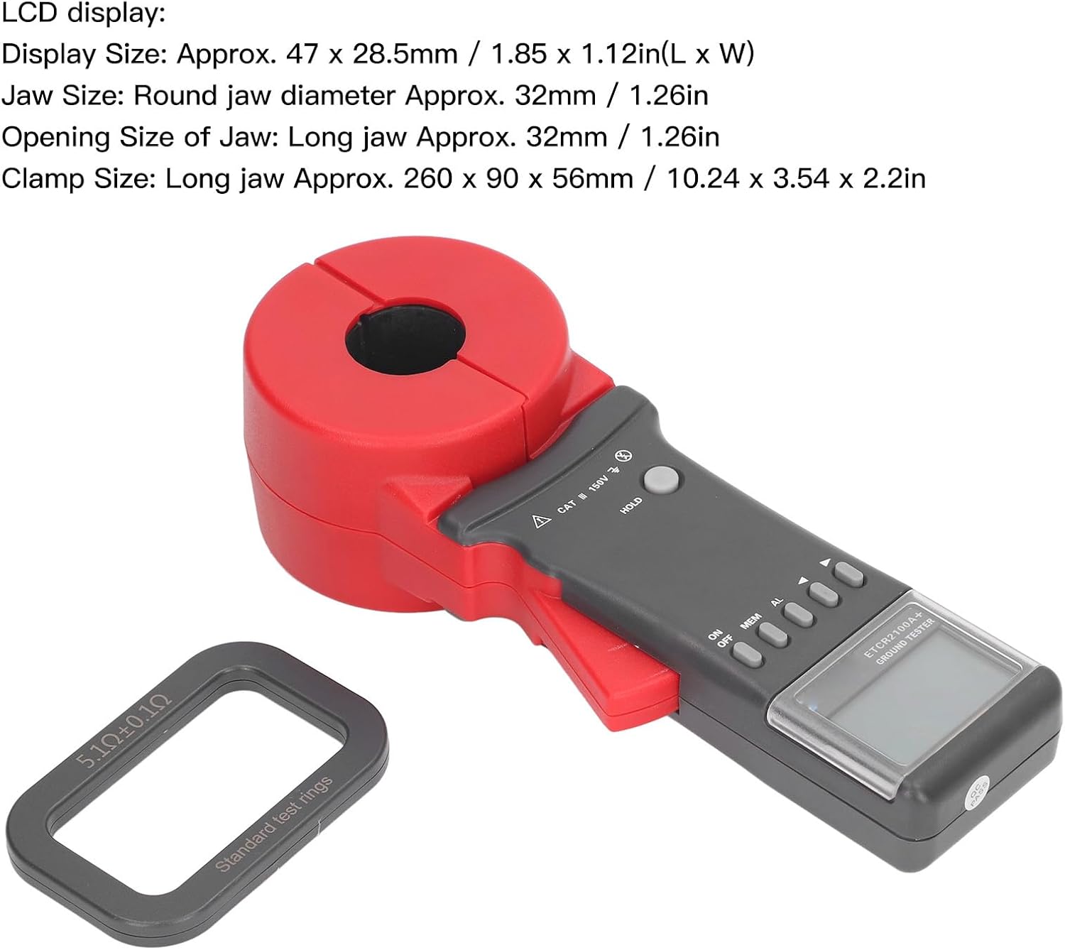
Image 1.1: The Tyenaza ETCR2100A+ Digital Clamp Resistance Tester, showing its overall design with the clamp jaw and control panel.
2. Información de seguridade
Always observe the following safety precautions to avoid electric shock, injury, or damage to the instrument:
- Non empregue o instrumento se parece estar danado ou funciona de forma anormal.
- Asegúrese de que o compartimento da batería estea ben pechado antes da operación.
- Non intente medir circuítos con tensión máis alá do volume especificado.tage limits (CAT III 150V).
- Avoid using the instrument in wet environments or during thunderstorms.
- Refer to qualified personnel for any repairs or servicing.
- Keep the instrument away from strong magnetic fields and electric fields exceeding specified limits.
3. Contido do paquete
Verifica que todos os elementos estean presentes no paquete:
- 1 x ETCR2100A+ Digital Clamp Probador de resistencia
- 1 x Accessory (likely a test ring or similar calibration aid)
- 1 x Manual de usuario (este documento)
- 1 x Caixa de almacenamento
Note: 1.5V AA batteries (x4) are required and are not included in the package.

Image 3.1: The ETCR2100A+ tester shown with a standard test ring, which is typically included as an accessory for calibration or verification.
4. Características do produto
The ETCR2100A+ Digital Clamp Resistance Tester offers the following key features:
- Pantalla multifuncional: Resistance and current values are displayed simultaneously on a new black luxury screen.
- Alta precisión: Microprocessor-controlled for precise grounding resistance detection, utilizing fast filtering technology to minimize interference.
- Xestión de datos: Features real-time clock, data storage for up to 99 sets, and data retrieval capabilities.
- Alarma audible e visual: "Beep beep beep" alarm sound with adjustable threshold settings for resistance (1-199 Ω) and current (1-499mA).
- Funcións automáticas: Automatic shutdown and fully automatic gear shifting for ease of use.
- Deseño robusto: Shockproof and dustproof structure, suitable for demanding industrial environments.
- Aplicación ampla: Ideal for telecommunications, power, meteorology, computer rooms, oil fields, power distribution lines, tower transmission lines, gas stations, factory grounding grids, and lightning rod systems.

Imaxe 4.1: Primeiro plano view of the robust clamp jaws, highlighting the double insulation and structural features designed for durability and safety.
5. Configuración
5.1 Instalación da batería
The ETCR2100A+ requires four (4) 1.5V AA batteries (not included).
- Locate the battery compartment cover on the back of the instrument.
- Use a suitable tool (if necessary) to open the battery compartment.
- Insert four 1.5V AA batteries, ensuring correct polarity (+/-) as indicated inside the compartment.
- Pecha a tapa do compartimento da batería de forma segura.
5.2 Encendido inicial
Despois da instalación da batería, prema o botón ON/OFF button to power on the device. The LCD display will illuminate, indicating the device is ready for use.
6. Instrucións de funcionamento
6.1 Medición básica
To perform a grounding resistance test:
- Asegúrese de que o instrumento está acendido.
- Abre o clamp mandíbulas premendo o gatillo.
- Coloque o clamp around the grounding conductor or circuit to be measured. Ensure the jaws are fully closed around the conductor.
- The resistance value will be displayed on the LCD screen. The device features fully automatic shifting.
- The single measurement time is approximately 0.5 seconds.
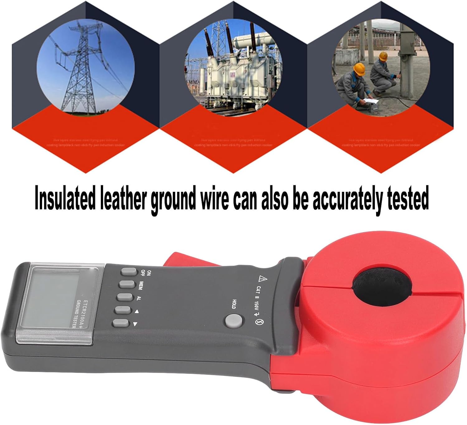
Image 6.1: The ETCR2100A+ tester shown clamping an insulated ground wire, demonstrating its capability to accurately test even insulated conductors.
6.2 Single Point Grounding System, Auxiliary Measurement
For single point grounding systems where direct clamp measurement of the lead wire is not feasible, auxiliary methods can be used. The two-point method is illustrated below:

Image 6.2: Diagram showing the two-point method for auxiliary grounding resistance measurement. It depicts a grounding rod (RA) connected to a single point, with a wire extending to a natural grounding point (e.g., water pipe, buried metal) for measurement.
Para usar este método:
- Identify a natural grounding point with a low resistance value near the grounding point to be measured. Examples include a water pipe, fire hydrant, or other deeply buried metal structure.
- Connect a wire from the point to be measured to this auxiliary grounding point.
- Clamp the ETCR2100A+ around the connecting wire to perform the measurement.
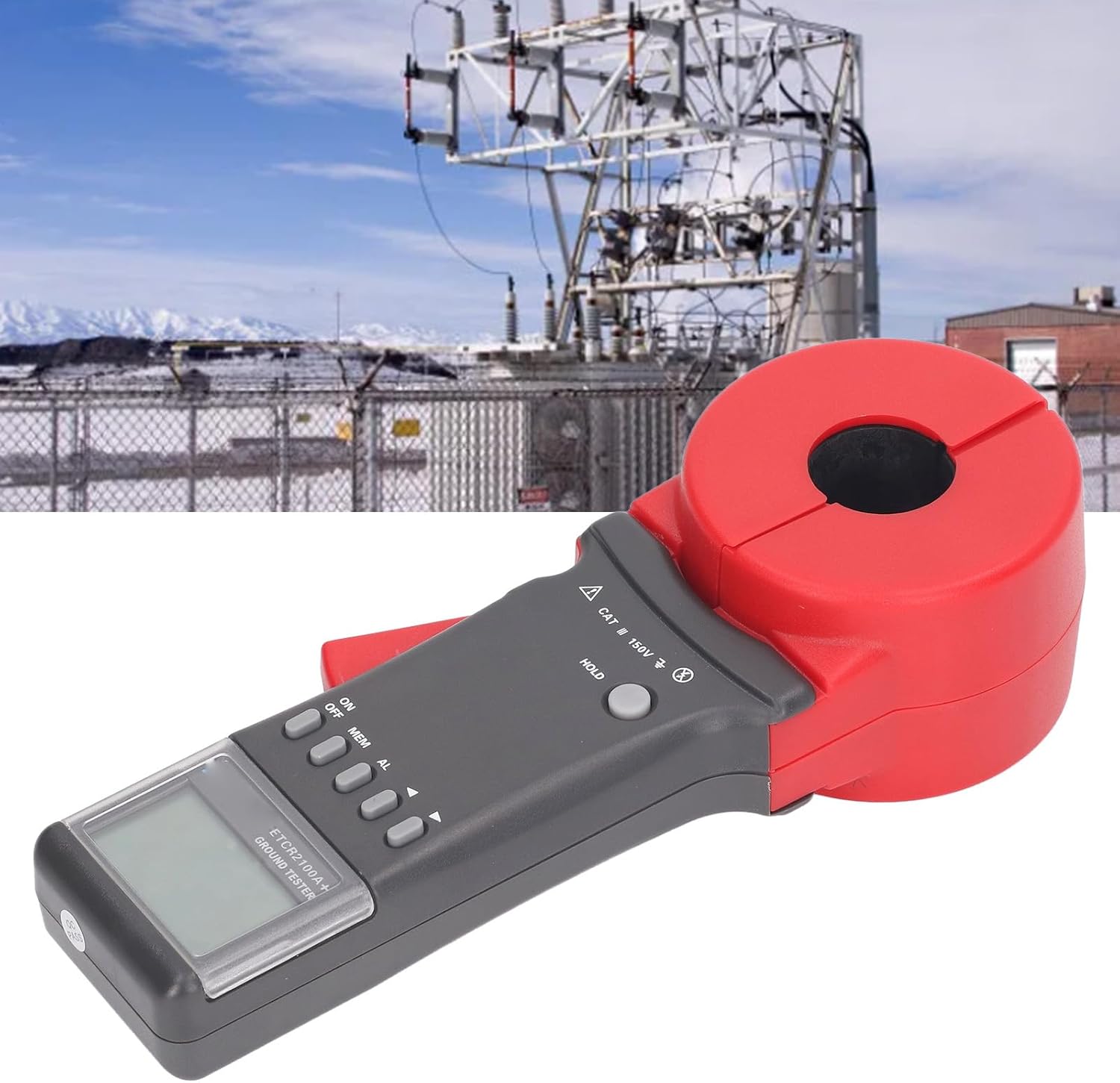
Image 6.3: The ETCR2100A+ tester positioned in an industrial substation, illustrating a typical application environment for grounding resistance measurement.
6.3 Almacenamento e recuperación de datos
The instrument can store up to 99 sets of measurement data.
- To store data: After a measurement, press the MEM button to save the current reading.
- To retrieve data: Press the MEM button repeatedly to cycle through stored data.
6.4 Función de alarma
The ETCR2100A+ features an audible and visual alarm for out-of-range measurements.
- To activate/deactivate the alarm: Press the AL botón.
- To set alarm thresholds: Refer to the device's on-screen menu or specific instructions for setting resistance (1-199 Ω) and current (1-499mA) alarm limits.

Image 6.4: A hand holding the ETCR2100A+ tester, demonstrating its ergonomic design and ease of handling during operation.
7. Mantemento
7.1 Limpeza
Wipe the instrument's exterior with a soft, damp pano. Non empregue produtos de limpeza abrasivos nin disolventes. Asegúrese de que o dispositivo estea apagado antes de limpalo.
7.2 Almacenamento
When not in use for extended periods, remove the batteries to prevent leakage. Store the instrument in its provided storage box in a cool, dry place, away from direct sunlight and extreme temperatures.
7.3 Calibración
Regular calibration by qualified personnel is recommended to maintain measurement accuracy, especially after prolonged use or if accuracy is suspected to be compromised.
8 Solución de problemas
| Problema | Causa posible | Solución |
|---|---|---|
| O dispositivo non se acende. | Baterías gastadas ou instaladas incorrectamente. | Replace batteries with new 1.5V AA batteries, ensuring correct polarity. |
| Lecturas inexactas. | Jaws not fully closed; interference from external fields; dirty jaws; need for calibration. | Ensure jaws are fully closed. Move away from strong magnetic/electric fields. Clean jaws. Consider professional calibration. |
| A alarma soa continuamente. | Measurement exceeds set alarm threshold. | Check the measured value against the set alarm limits. Press the AL button to silence or deactivate the alarm. |
| A pantalla está en branco ou parpadea. | Low battery power; environmental conditions (extreme temperature/humidity). | Replace batteries. Operate within specified temperature and humidity ranges (-20 ℃ to 55 ℃; 10% RH to 90% RH). |
9. Especificacións
| Modelo | ETCR2100A+ |
| Función | Grounding resistance test, circuit resistance test, leakage current test |
| Rango de resistencia | 0.01 Ω a 200 Ω |
| Resolución de resistencia | 0.001 Ω |
| Rango actual | None (for leakage current test, the range is 1-499mA for alarm setting) |
| Almacenamento de datos | 99 conxuntos |
| Alarm Threshold Setting Range (Resistance) | 1-199 Ω |
| Alarm Threshold Setting Range (Current) | 1-499 mA |
| Temperatura e humidade de traballo | -20 ℃ to 55 ℃; 10% RH to 90% RH |
| Pantalla LCD | 4 digit LCD digital display |
| Tamaño de visualización | Approx. 47 x 28.5mm / 1.85 x 1.12in (L x W) |
| Jaw Size (Round) | Approx. 32mm / 1.26in diameter |
| Jaw Opening Size (Long) | Aprox. 32 mm / 1.26 polgadas |
| Clamp Size (Long Jaw) | Aprox. 260 x 90 x 56 mm / 10.24 x 3.54 x 2.2 polgadas |
| Nivel de protección | Dobre illamento |
| Características estruturais | Clamp shaped CT |
| Cambio de marchas | Fully automatic shifting |
| Campo magnético externo | <40A / m |
| Campo eléctrico externo | <1 V / m |
| Tempo de medición única | 0.5 segundos |
| Resistance Measurement Frequency | Greater than 1KHz |
| Tested Current Frequency | 50/60Hz automatic |
| Fonte de alimentación | 4 pilas AA de 1.5 V (non incluídas) |
| Material | ABS |
| Peso do elemento | 2.13 quilogramos / 4.69 libras |
10. Garantía e soporte
Para obter información sobre a garantía, asistencia técnica ou consultas sobre o servizo, póñase en contacto co seu vendedor ou directamente co fabricante. Garde o recibo de compra como proba de compra.
Manufacturer: Tyenaza
Ask a question about this manual
Ask about setup, troubleshooting, compatibility, parts, safety, or missing instructions. Manuals+ will review the question and use this page’s manual context to help answer it.