1. Introdución
This manual provides detailed instructions for the safe and effective operation of the FKM TS-18B Digital Clamp Meter. This True-RMS 6000 counts auto-ranging multimeter is designed for measuring AC current, AC/DC voltage, frequency, duty cycle, resistance, capacitance, diode, continuity, and temperature. It also features Non-Contact Voltage (NCV) detection and live/zero wire discrimination, making it suitable for various electrical troubleshooting tasks in household, automotive, and industrial settings.

Image 1.1: The FKM TS-18B Digital Clamp Meter shown with its included test leads, thermocouple, batteries, and storage bag.
2. Información de seguridade
Read all safety warnings and instructions carefully before using this instrument. Failure to follow these instructions may result in electric shock, fire, or serious injury.
- This instrument complies with IEC61010-2-032 safety standards, CAT III 600V, and Pollution Class 2.
- Non exceda os valores de entrada máximos especificados para cada rango de medición.
- Always ensure the test leads are properly connected and the function switch is set to the correct range before making measurements.
- Ao medir a corrente alterna co clamp mandíbula, clamp só un of the wires, not the entire power cord. Clamping both wires will result in an inaccurate reading as the magnetic fields cancel each other out. The clamp jaw is exclusively for current measurement; do not use it to measure voltage.
- Teña coidado ao traballar co voltagpor riba de 30 V CA RMS, 42 V pico ou 60 V CC, xa que supoñen un perigo de descarga eléctrica.
- Substitúa as pilas inmediatamente cando apareza o indicador de pila baixa para garantir lecturas precisas.
- Do not operate the meter if it appears damaged or if the test leads are compromised.
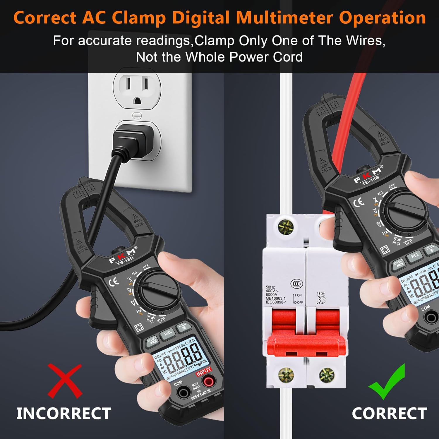
Image 2.1: Illustration of the correct method for measuring AC current by clamping only a single conductor, not the entire power cord.
3. Produto rematadoview
3.1 Compoñentes

Image 3.1: Labeled diagram of the FKM TS-18B Clamp Meter, indicating the NCV sensor probe, clamp body light, lever for jaw opening/closing, rotatory range selector, relative measurement button, data hold/backlight button, LCD, COM terminal, and input terminal.
- Clamp Mandíbula: Used for non-contact AC current measurement. Maximum opening size is 25mm.
- NCV Sensor Probe: Detecta volume sen contactotage.
- Rotary Range Selector: Used to select measurement functions.
- Pantalla LCD: Mostra lecturas de medición, unidades e indicadores.
- Input Terminals (COM, INPUT): Para conectar cables de proba para vol.tage, resistance, capacitance, diode, continuity, frequency, and temperature measurements.
- Botóns: SELECT/Flashlight, REL (Relative Measurement), HOLD/* (Data Hold/Backlight).
- Linterna LED: Ilumina a área de medición.
3.2 Características principais
- True-RMS 6000 Counts Display
- Auto-ranging for simplified operation
- Measures AC Current, AC/DC Voltage, Frequency, Duty Cycle, Resistance, Capacitance, Diode, Continuity, Temperature
- Vol. Sen contactotagDetección e (NCV).
- Live/Zero Wire Discrimination
- Backlit LCD and LED Flashlight for low-light conditions
- Función de retención de datos para conxelar lecturas
- Relative Measurement (REL) mode
- Indicador de batería baixa
- Automatic Power-Off after 15 minutes of inactivity

Image 3.2: Visual representation of the FKM TS-18B's multiple functions, including AC/DC Voltage, AC Current, NCV, Frequency, Resistance, Capacitance, Diode, True RMS, Temperature, Flashlight, Relative Measurement, HD Backlight, and Automatic Shutdown.
4. Configuración
4.1 Instalación da batería
- Ensure the meter is turned OFF and test leads are disconnected.
- Localice o compartimento das baterías na parte traseira do medidor.
- Use un desaparafusador para abrir a tapa da batería.
- Insert two 1.5V AAA batteries, observing correct polarity.
- Replace the battery cover and fasten the screw tightly.

Image 4.1: Instructions for replacing the batteries in the FKM TS-18B, showing the location of the battery compartment and the use of AAA batteries.
5. Instrucións de funcionamento
Turn the rotary range selector to the desired function. Connect test leads to the COM and INPUT terminals as required for the measurement type.
5.1 Medición de corrente alterna
- Set the rotary switch to the 'A~' position.
- Abre o clamp jaw using the lever.
- Encerrar só un condutor do circuíto dentro do clamp jaw. Ensure the conductor is centered.
- Read the AC current value on the LCD.
5.2 AC/DC Voltage Medición
- Axuste o interruptor rotatorio á posición 'V~' (Volumen CAtage) ou 'V=' (Volumen de CCtage) posición.
- Insert the black test lead into the COM terminal and the red test lead into the INPUT terminal.
- Conecte as sondas de proba ao circuíto ou compoñente que se vai medir.
- Le o voltagValor na pantalla LCD.

Image 5.1: The FKM TS-18B demonstrating measurements of AC Voltage using test leads, DC Voltage from a battery, and AC Current using the clamp jaw on a single wire.
5.3 Resistance, Capacitance, Diode, Continuity Measurement
- Set the rotary switch to the 'Ω/C/Diode/Continuity' position. Use the SELECT button to cycle through these functions.
- Insert the black test lead into the COM terminal and the red test lead into the INPUT terminal.
- Connect the test probes across the component. For resistance and capacitance, ensure the component is de-energized.
- For continuity, a buzzer will sound if resistance is below a certain threshold.
- Le o valor na pantalla LCD.

Image 5.2: The FKM TS-18B showing measurements for Resistance, Capacitance, Continuity (Buzzer), and Diode testing using test leads.
5.4 Frequency (Hz) and Duty Cycle (%) Measurement
- Set the rotary switch to the 'Hz/%' position.
- Insert the black test lead into the COM terminal and the red test lead into the INPUT terminal.
- Connect the test probes across the circuit where frequency or duty cycle is to be measured.
- Read the frequency or duty cycle value on the LCD. Use the SELECT button to switch between Hz and %.

Image 5.3: The FKM TS-18B displaying measurements for Frequency (Hz) and Duty Cycle (%).
5.5 Medición da temperatura
- Set the rotary switch to the '°C/°F' position.
- Insert the thermocouple into the INPUT and COM terminals, observing polarity.
- Coloque a sonda do termopar no punto onde se vai medir a temperatura.
- Read the temperature value on the LCD. Use the SELECT button to switch between Celsius and Fahrenheit.

Image 5.4: The FKM TS-18B measuring temperatures of hot liquid, an air conditioner vent, and ice using the included thermocouple.
5.6 Vol. sen contactotagDetección e (NCV).
- Axuste o interruptor rotatorio á posición "NCV".
- Move the NCV sensor probe (top of the clamp mandíbula) preto do condutor ou da toma de corrente.
- The meter will emit an audible beep and the LCD will show dashes ('---' or '----') with increasing frequency as voltage é detectado.
Image 5.5: The FKM TS-18B performing Non-Contact Voltage (NCV) detection near an electrical outlet, indicating voltage presence with sound and visual cues.
5.7 Live/Zero Wire Discrimination
- Set the rotary switch to the 'N/L' position.
- Insira o cable de proba vermello no terminal INPUT.
- Touch the red probe to the wire to be tested.
- The meter will indicate if it is a Live or Zero wire.
5.8 Retención de datos e retroiluminación
- Press the 'HOLD/*' button briefly to freeze the current reading on the display. Press again to release.
- Press and hold the 'HOLD/*' button for approximately 2 seconds to turn the backlight ON or OFF. The backlight automatically turns off after 30 seconds to conserve power.
5.9 Apagado automático
The meter will automatically power off after approximately 15 minutes of inactivity to conserve battery life. To reactivate, turn the rotary switch to OFF and then back to the desired function, or press any button.

Image 5.6: The FKM TS-18B showing its backlit display and activated LED flashlight, highlighting its readability in dim conditions and the auto-shutdown feature.
6. Mantemento
6.1 Limpeza
Limpar a superficie c do medidorasing con anuncioamp un pano e un deterxente suave. Non empregue abrasivos nin solventes. Asegúrese de que o medidor estea seco antes de usalo.
6.2 Substitución da batería
Refer to Section 4.1 for detailed instructions on battery replacement. Always replace both batteries with new 1.5V AAA batteries when the low battery indicator appears on the display.
7 Solución de problemas
- Sen pantalla/o medidor non se acende: Comprobe a instalación das baterías e asegúrese de que non estean esgotadas. Substitúaas se é necesario.
- Lecturas inexactas:
- Asegúrese de que estea seleccionada a función correcta no interruptor rotatorio.
- Verify test leads are securely connected and not damaged.
- For AC current, ensure only one wire is clamped.
- Check for external interference or strong magnetic fields.
- Pantalla "OL": Indicates an overload or out-of-range measurement. Select a higher range if available, or verify the circuit conditions.
- Blinking Display: May indicate a low battery condition. Replace batteries.
8. Especificacións
| Característica | Especificación |
|---|---|
| Número de modelo | TS-18B |
| Mostrar | 6000 Counts, True-RMS |
| Rango de corrente alterna | Up to 600A (AC only) |
| AC / DC Voltage Alcance | Ata 600V |
| Rango de resistencia | Ata 60 MΩ |
| Rango de capacitancias | Ata 60 mF |
| Rango de frecuencias | 10 Hz a 10 MHz |
| Rango de temperatura | -40 °F a 1832 °F (-40 °C a 1000 °C) |
| Fonte de enerxía | 2 pilas AAA de 1.5 V (incluídas) |
| Valoración de seguridade | IEC61010-2-032, CAT III 600V, Pollution Class 2 |
| Clamp Tamaño de apertura | 25 mm (1 polgadas) |
| Apagado automático | Aprox. 15 minutos |
9. Contido do paquete
The FKM TS-18B Digital Clamp Meter package includes:
- 1 x FKM TS-18B Digital Clamp Contador
- 1 x par de cables de proba
- 1 termopar
- 2 x pilas AAA
- 1 x Manual de instrucións (este documento)
- 1 x bolsa de almacenamento

Image 9.1: Visual representation of the FKM TS-18B package contents, including the meter, test leads, thermocouple, batteries, and carrying case.
10. Garantía e soporte
FKM provides lifelong service and technical support for the TS-18B Digital Clamp Meter. For any questions, technical assistance, or warranty claims, please contact FKM customer support through the retailer where the product was purchased or visit the official FKM websitio.