Produto rematadoview
The Armstrong R40403-003 blower control circuit board is designed to replace previous versions R40403-001, R40403-002, and ST9120A, B, or C blower controls. This board manages a 2-speed indoor blower motor and a single-speed inducer motor. It processes inputs from the thermostat (W, Y, and G terminals), pressure switch, and high-temperature limit switches. The control also features user-selectable blower delays via DIP switch settings. A 5-amp replaceable automotive-type fuse protects the 24-volt circuit.

Image 1: The Armstrong R40403-003 Blower Control Circuit Board. This image displays the front view of the circuit board, showing various electronic components, relays, terminals, and DIP switches.
Información de seguridade
Always disconnect power to the furnace at the main breaker before attempting any installation, maintenance, or troubleshooting. Failure to do so can result in electrical shock, personal injury, or death. Installation should only be performed by qualified personnel. Ensure all wiring connections comply with local and national electrical codes.
- Desconexión de alimentación: Turn off power at the circuit breaker before handling the board.
- Descarga estática: Handle the circuit board by its edges to avoid damage from static electricity.
- Protección por fusibles: The 24-volt circuit is protected by a 5-amp automotive-type fuse. Replace only with a fuse of the same rating.
Configuración e instalación
This section provides general guidelines for replacing the Armstrong R40403-003 blower control board. Refer to your furnace's specific wiring diagram for detailed instructions.
- Apagado: Ensure all power to the furnace unit is disconnected at the main electrical breaker. Verify with a voltagprobador.
- Acceder ao taboleiro antigo: Locate and access the existing blower control board within your furnace.
- Cableado de documentos: Before disconnecting any wires, take clear photographs of all connections to the old board. Label each wire if necessary.
- Desconectar os cables: Desconecte con coidado todos os cables da antiga placa de control.
- Eliminar a placa antiga: Desatornille ou solte a placa antiga do seu soporte.
- Montar unha nova placa: Secure the new Armstrong R40403-003 board in the same location using the existing mounting hardware.
- Conecte cables: Reconnect all wires to the new board, matching them precisely to the documented connections from the old board. Pay close attention to the transformer leads (C and X terminals). The X lead from the old board typically connects to the XFRMR terminal on the new board.
- Configuración do interruptor DIP: Adjust the DIP switches on the new board to match the settings of your previous board or according to your furnace's specifications for blower delays.
- Inspeccionar conexións: Double-check all wiring connections for security and correctness.
- Restaurar enerxía: Once all connections are verified, restore power to the furnace at the main breaker.
- Proba de funcionamento: Initiate a heating or cooling cycle to confirm proper operation of the furnace and blower.
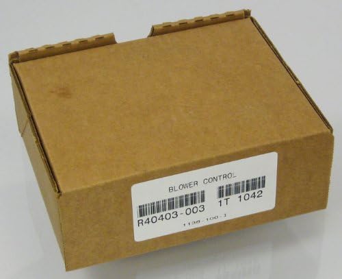
Image 2: The Armstrong R40403-003 Blower Control Circuit Board in its packaging. This image shows the brown cardboard box with a product label indicating "BLOWER CONTROL" and the model number R40403-003.
Principios de funcionamento
The R40403-003 board functions as the central control for the furnace's blower and inducer motors. It receives signals from the thermostat to initiate heating or cooling cycles. The board then activates the appropriate motors and monitors safety limits such as the pressure switch and high-temperature limit switches to ensure safe operation. User-selectable DIP switch settings allow for customization of blower delays, which control how long the blower runs after the heating or cooling call ends, helping to maximize system efficiency and comfort.
Blower Delay Settings
The board features DIP switches to adjust blower delays. Consult your furnace manual or the wiring diagram provided with the board for specific delay settings and their corresponding switch configurations. Typical settings include delays for fan off after heating, and fan on/off for cooling cycles.
Mantemento
The Armstrong R40403-003 blower control board is designed for reliable operation and generally requires minimal maintenance. However, periodic checks of the furnace system are recommended.
- Inspección de fusibles: Periodically inspect the 5-amp automotive-type fuse on the board. If the fuse is blown, replace it only with a fuse of the exact same rating (5 amp). A blown fuse often indicates an underlying electrical issue that should be investigated.
- Conexións de cableado: Annually, or during routine furnace maintenance, inspect all wiring connections to the board to ensure they are secure and free from corrosion.
- Limpeza: Keep the area around the circuit board clean and free from dust and debris, which can impede proper function or lead to overheating.
Resolución de problemas
This section provides basic troubleshooting steps for common issues related to the blower control board. For complex problems, consult a qualified HVAC technician.
| Problema | Causa posible | Solución |
|---|---|---|
| Furnace not starting / No power to board | Blown fuse on board, tripped circuit breaker, loose wiring connection. | Check and replace 5-amp fuse. Reset circuit breaker. Inspect and secure all power connections. |
| O motor do ventilador non funciona | Incorrect thermostat input, faulty pressure switch, high-limit switch tripped, motor issue, board malfunction. | Verify thermostat settings. Check pressure switch and high-limit switch for continuity. Consult HVAC technician for motor or board diagnosis. |
| O ventilador funciona continuamente | Thermostat fan setting "ON", stuck relay on board, incorrect DIP switch setting. | Set thermostat fan to "AUTO". Check DIP switch settings for blower delays. If issue persists, board may need replacement. |
| Inducer motor not running | Faulty inducer motor, pressure switch issue, board malfunction. | Check inducer motor for power. Verify pressure switch operation. If necessary, consult a professional. |
Especificacións
Key technical specifications for the Armstrong R40403-003 Blower Control Circuit Board:
- Número de modelo: R40403-003
- Substitúe os modelos: R40403-001, R40403-002, 20054502, ST9120A, B, C
- Liña Operativa Voltage: 85 a 135 VCA, 50/60 Hz
- Secondary Control Voltage: 18.0 a 30.0 VCA, 50/60 Hz
- Maximum Blower Loading: 15FLA, 30LRA @ 120 VAC; 7.5FLA, 15LRA @ 240 VAC
- Maximum Inducer Loading: 3FLA, 10LRA @ 120 VAC; 1.5FLA, 5LRA @ 240 VAC
- Protección por fusibles: 5 Amp replaceable automotive type fuse (24-volt circuit)
- Dimensións: Aproximadamente 7.8 x 6.3 x 3 polgadas
- Peso: Aproximadamente 0.16 onzas
- Fabricante: Armstrong
Garantía e Soporte
Specific warranty information for the Armstrong R40403-003 Blower Control Circuit Board is not provided in this manual. For details regarding warranty coverage, terms, and conditions, please refer to the product packaging or contact Armstrong customer support directly. For technical assistance or professional installation, it is recommended to consult a certified HVAC technician.
You may visit the official Armstrong website or contact their customer service for further support.
- Fabricante: Armstrong
- Websitio: www.armstrongair.com (General Armstrong HVAC site, as no specific product support link is provided)


