1. Introdución
This manual provides comprehensive instructions for the installation, operation, and maintenance of the Supermicro X10SLM+-LN4F motherboard. Designed for server applications, this motherboard features an LGA1150 socket, Intel C224 PCH, DDR3 memory support, and multiple Gigabit Ethernet ports. Please read this manual thoroughly before proceeding with installation to ensure proper setup and optimal performance.
2. Produto rematadoview
The Supermicro X10SLM+-LN4F is a microATX server motherboard built for reliability and performance. Key features include:
- LGA1150 Socket for Intel Xeon E3-1200 v3/v4 and 4th Gen Core i3 processors.
- Intel C224 PCH chipset.
- Four DDR3 DIMM slots supporting up to 64GB ECC/non-ECC UDIMM.
- Multiple SATA3 (6Gbps) ports.
- Integrated quad Gigabit Ethernet ports.
- USB 3.0 and USB 2.0 support.
- VGA output for integrated graphics.
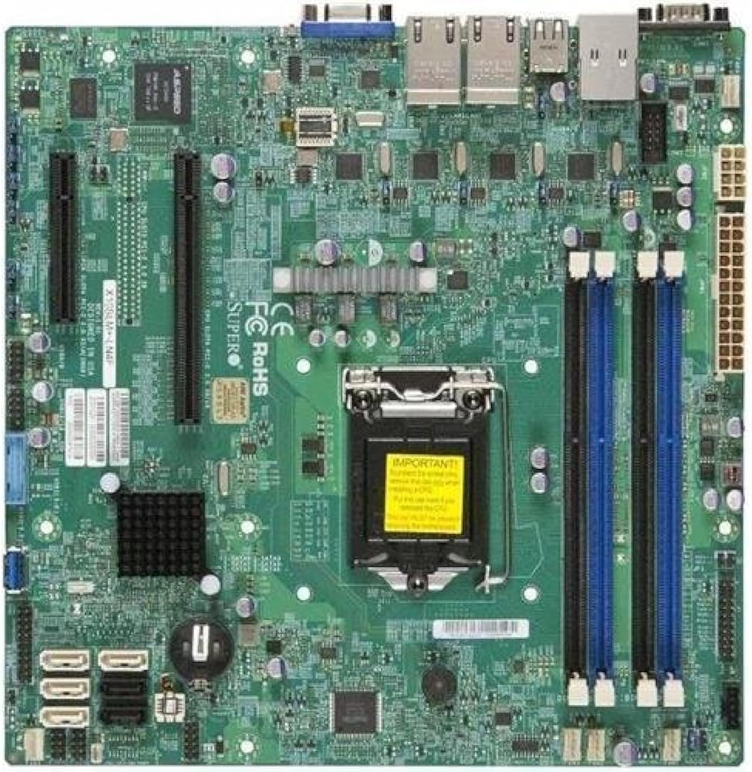
Figura 2.1: Arriba abaixo view of the Supermicro X10SLM+-LN4F motherboard, showing the CPU socket, DIMM slots, PCIe slots, and various connectors.

Figura 2.2: En ángulo view of the motherboard, highlighting the layout of components and expansion slots.
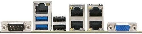
Figura 2.3: Rear I/O panel of the Supermicro X10SLM+-LN4F motherboard, featuring multiple LAN ports, USB ports, and serial ports.
3. Configuración e instalación
Before beginning installation, ensure your system is powered off and disconnected from the power source. Wear an anti-static wrist strap to prevent electrostatic discharge (ESD) damage to components.
3.1. Instalación da CPU
- Localiza o socket da CPU LGA1150 na placa base.
- Empuxe suavemente a palanca de carga cara abaixo e tírea cara a un lado para abrir o marco de retención do socket da CPU.
- Aliña coidadosamente a marca triangular da CPU coa marca correspondente no socket.
- Coloca a CPU no socket sen forzala.
- Close the retention frame and secure it with the load lever.
- Aplique unha capa fina e uniforme de pasta térmica no difusor de calor (IHS) integrado da CPU.
- Instala o refrigerador da CPU segundo as instrucións do fabricante.
3.2. Instalación da memoria (RAM)
- Locate the four DDR3 DIMM slots. For optimal performance, refer to the motherboard's specific memory population guidelines, typically starting with slots closest to the CPU or specific colored slots for dual-channel configurations.
- Abra os clips de retención en ambos extremos da ranura DIMM.
- Aliñe a muesca do módulo de memoria DDR3 coa chave da ranura DIMM.
- Insert the memory module firmly into the slot until the retention clips snap into place.
- Asegúrate de que ambos os clips estean completamente pechados e que o módulo estea correctamente asentado.
3.3. Instalación do dispositivo de almacenamento
Connect SATA storage devices (HDDs/SSDs) to the SATA ports on the motherboard using SATA data cables. Connect the power cables from your power supply unit (PSU) to the storage devices.
3.4. Instalación da tarxeta de expansión
This motherboard features PCI Express (PCIe) slots. To install an expansion card:
- Remove the corresponding slot cover from your chassis.
- Aliñe a tarxeta de expansión coa ranura PCIe.
- Prema firmemente ata que a tarxeta estea completamente asentada na ranura.
- Secure the card with a screw or retention clip from your chassis.
3.5. Conexións de alimentación
- Conector de alimentación ATX de 24 pines: Connect the main 24-pin power cable from your PSU to the ATX power connector on the motherboard.
- 8-pin EPS/CPU Power Connector: Connect the 8-pin (or 4+4 pin) CPU power cable from your PSU to the EPS connector near the CPU socket.
3.6. Conexións de E/S do panel frontal e traseiro
- Conectores do panel frontal: Connect the power switch, reset switch, power LED, and HDD activity LED cables from your chassis to the corresponding pins on the motherboard's front panel header. Refer to the motherboard's silkscreen labels for correct orientation.
- Cabeceiras USB: Connect front panel USB ports to the onboard USB headers.
- Audio Headers: Connect front panel audio jacks to the onboard audio header.
- Panel de E/S traseiro: Connect peripherals such as keyboard, mouse, monitor (via VGA), and network cables (to the Gigabit Ethernet ports) to the rear I/O panel.
4. Instrucións de funcionamento
4.1. Acendido inicial e configuración da BIOS/UEFI
- After all components are installed and connected, connect the power cord to the PSU and turn on the power switch on the PSU.
- Press the power button on your chassis.
- During the Power-On Self-Test (POST), repeatedly press the DEL or F2 key (or as indicated on screen) to enter the BIOS/UEFI setup utility.
- In the BIOS/UEFI, configure essential settings such as date and time, boot order, and enable/disable specific features as required for your operating system and hardware.
- Garda os cambios e sae da BIOS/UEFI. O sistema reiniciarase.
4.2. Instalación do sistema operativo
To install an operating system (e.g., Windows, Linux, VMware ESXi):
- Insert the operating system installation media (USB drive or DVD) into the system.
- Boot from the installation media (you may need to adjust the boot order in BIOS/UEFI).
- Follow the on-screen prompts to install the operating system on your chosen storage device.
- After installation, install all necessary drivers for the motherboard components (chipset, LAN, VGA, etc.) from the Supermicro website or the provided driver disc.
5. Mantemento
Un mantemento regular axuda a garantir a lonxevidade e o funcionamento estable da placa base e do sistema.
5.1. Limpeza
- Limpa periodicamente o po da placa base e dos compoñentes do sistema con aire comprimido. Asegúrate de que o sistema estea apagado e desconectado antes de limpalo.
- Evite usar produtos de limpeza líquidos directamente sobre os compoñentes.
- Ensure proper airflow within the chassis by keeping fan vents clear.
5.2. Firmware and Driver Updates
- Comproba o Supermicro website periodically for updated BIOS/UEFI firmware and drivers for your motherboard model.
- Follow the provided instructions carefully when updating firmware to avoid system instability.
5.3. Consideracións ambientais
- Operate the motherboard within recommended temperature and humidity ranges to prevent damage.
- Ensure adequate ventilation in the server chassis.
6 Solución de problemas
Esta sección ofrece solucións a problemas comúns cos que podes atoparte.
6.1. Sen alimentación / Sen POST (autoproba de acendido)
- Verify that the power supply unit (PSU) is connected correctly to the motherboard (24-pin ATX and 8-pin EPS connectors).
- Ensure the PSU is switched on and receiving power from the wall outlet.
- Check that the front panel power switch cable is correctly connected to the motherboard header.
- Reseat the CPU, RAM modules, and any expansion cards.
- Try booting with only essential components (CPU, one RAM stick, CPU cooler) to isolate the issue.
- Listen for beep codes from the system speaker, which can indicate specific hardware failures. Refer to the Supermicro website for beep code interpretations.
6.2. Problemas de visualización
- Ensure the monitor is properly connected to the motherboard's VGA port.
- Verifique que o monitor estea acendido e configurado na fonte de entrada correcta.
- If using a discrete graphics card, ensure it is properly seated and connected to power (if required).
6.3. Operating System Not Booting
- Check the boot order in the BIOS/UEFI to ensure the correct storage device is prioritized.
- Verify that the operating system is installed correctly on the storage device.
- Ensure SATA data and power cables are securely connected to the storage device and motherboard.
7. Especificacións
Below are the technical specifications for the Supermicro X10SLM+-LN4F motherboard:
| Característica | Detalle |
|---|---|
| Marca | Supermicro |
| Nome do modelo | X10SLM+-LN4F-B |
| Socket CPU | LGA1150 |
| Tipo de chipset | Intel C224 |
| Tecnoloxía de memoria RAM | SDRAM DDR3 |
| Velocidade da memoria | 1600 MHz |
| Capacidade de almacenamento da memoria | Ata 64 GB |
| Número de portos USB 2.0 | 2 (E/S traseira) |
| Interfaz da tarxeta gráfica | Integrated, PCI |
| Dispositivos compatibles | Servidor |
| Plataforma | Windows 10 |
| Peso do elemento | 5.8 libras |
| Dimensións do produto (LxWxH) | 10 x 10 x 2 polgadas |
| Data de primeira dispoñibilidade | 4 de xuño de 2013 |
Note: Specifications are subject to change without notice. For the most current information, please refer to the official Supermicro product page.
8. Garantía e soporte
For detailed warranty information, please refer to the warranty card included with your product or visit the official Supermicro website. Technical support is available through Supermicro's customer service channels, including their support portal, email, and phone. Please have your product model number (X10SLM+-LN4F) and serial number ready when contacting support.
For the latest drivers, BIOS updates, and additional documentation, please visit: www.supermicro.com


