1. Introdución
The Velleman Basic ARDUINO Compatible EXPERIMENTER'S KIT (Model B071R77ZCC) is designed for individuals interested in learning about electronics and microcontrollers. This kit provides a comprehensive set of components to perform various experiments, understand basic circuit design, and develop programming skills using an Arduino-compatible platform. It is suitable for beginners and hobbyists looking to explore the world of embedded systems.
2. Produto rematadoview and Kit Contents
This kit includes a variety of components essential for numerous electronic projects. Familiarize yourself with each item before beginning your experiments.
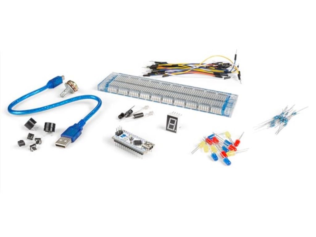
Image: The Velleman Basic ARDUINO Compatible EXPERIMENTER'S KIT, showcasing the main board, breadboard, and various electronic components included in the package.
Compoñentes do kit:
- 1x WPB102: Main Arduino-compatible development board.
- 1x cable USB: For connecting the WPB102 board to a computer.
- 1x Breadboard: For prototyping circuits without soldering.
- 30x Breadboard Jumper Wires: For making connections on the breadboard.
- 2x Photo Sensitive Transistors (SGPT5053C): For light detection experiments.
- 1x IR Remote Receiver: For receiving infrared signals from a remote control.
- 4x Tactile Switches: Momentary push buttons for input.
- 15x LEDs (different colors): Light Emitting Diodes for visual output.
- 1x Seven Segment Display: For displaying numerical digits.
- 1x Zumbador: For producing sound.
- 1x 50K Potentiometer: A variable resistor for analog input.
- 2x Tilt Switches: For detecting orientation or movement.
- 10x 220 Ohm Resistors: Common resistors for current limiting.
- 10x 1k Ohm Resistors: Common resistors for various circuit applications.
3. Instrucións de configuración
Follow these steps to set up your Velleman Basic ARDUINO Compatible EXPERIMENTER'S KIT and prepare for your first project.
- Desempaquetar e inspeccionar: Carefully remove all components from the packaging. Verify that all items listed in Section 2 are present and undamaged.
- Instalar Arduino IDE: Download and install the latest version of the Arduino Integrated Development Environment (IDE) from the official Arduino websitio (www.arduino.cc/en/software). This software is used to write, compile, and upload code to your WPB102 board.
- Connect the WPB102 Board: Connect one end of the provided USB cable to the WPB102 board and the other end to an available USB port on your computer. The board's power LED should illuminate, indicating it is receiving power.
- Install Drivers (if necessary): Your operating system may automatically install the necessary USB drivers. If not, refer to the Arduino IDE documentation or online resources for manual driver installation specific to your operating system and the WPB102 board.
- Select Board and Port in Arduino IDE: Open the Arduino IDE. Go to Ferramentas > Taboleiro and select the appropriate Arduino-compatible board (e.g., "Arduino Uno" or similar, depending on the WPB102's specific compatibility). Then, go to Ferramentas > Porto and select the serial port corresponding to your connected WPB102 board.
- Test Connection (Blink Sketch): Load the basic "Blink" example sketch (File > Examples > 01.Conceptos básicos > Blink). Upload this sketch to your board. If successful, the onboard LED on your WPB102 board should start blinking, confirming proper setup.
4. Instrucións de funcionamento
This section provides general guidance on using the components in your kit for various experiments. Detailed project instructions are typically found in accompanying guides or online tutorials.
4.1. Breadboard Usage
The breadboard allows you to build temporary circuits. The holes are internally connected in specific patterns:
- Raíles de alimentación: The long rows along the sides (marked with '+' and '-') are typically used for power supply (5V or 3.3V) and ground connections. All holes in a single power rail are connected.
- Component Area: The central area has columns of 5 holes that are connected vertically. Components are typically placed across the central gap, with each leg in a different column.
4.2. Basic Circuit Building Principles
- Resistencias: Always use a current-limiting resistor when connecting an LED to prevent it from burning out.
- Polaridade: Components like LEDs, photo transistors, and the seven-segment display are polarized. Ensure they are connected in the correct orientation (anode to positive, cathode to negative/ground).
- Conexións: Use jumper wires to connect components on the breadboard to each other and to the WPB102 board's digital and analog pins, as well as power (5V/3.3V) and ground (GND) pins.
4.3. Programming with Arduino IDE
The Arduino IDE uses a simplified C++ language. You will write "sketches" (programs) to control your WPB102 board and connected components.
- `setup()` function: This function runs once when the sketch starts after power-up or reset. It's used for initializing pin modes (INPUT/OUTPUT) and serial communication.
- `loop()` function: This function runs repeatedly forever after the `setup()` function completes. It contains the main logic of your program.
- Uploading Sketches: After writing your code, click the "Verify" button (checkmark icon) to check for errors, then click the "Upload" button (right arrow icon) to send the compiled code to your WPB102 board.
Refer to the extensive online Arduino community and tutorials for specific project ideas and code examples using the components provided in this kit.
5. Mantemento
Proper care and maintenance will extend the lifespan of your experimenter's kit components.
- Almacenamento: Store all components in a dry, cool place, away from direct sunlight and extreme temperatures. Use the original packaging or a dedicated storage box to keep small components organized and prevent loss.
- Manexo: Handle electronic components by their edges or body whenever possible to avoid touching pins, which can be sensitive to static electricity or oils from your skin.
- Limpeza: If necessary, gently clean the WPB102 board and other components with a soft, dry, lint-free cloth. Avoid using liquids or abrasive cleaners.
- Descarga estática: Be mindful of static electricity, which can damage sensitive electronic components. Work on an anti-static mat if available, or discharge yourself by touching a grounded metal object before handling components.
- Seguridade eléctrica: Always disconnect power from the WPB102 board before making or changing circuit connections on the breadboard.
6 Solución de problemas
Aquí tes algúns problemas comúns e as súas posibles solucións:
- WPB102 Board Not Powering On:
- Ensure the USB cable is securely connected to both the board and the computer.
- Try a different USB port or USB cable.
- Verify your computer's USB port is functioning correctly.
- Sketch Not Uploading:
- Check that the correct board type is selected under Ferramentas > Taboleiro no IDE de Arduino.
- Verify that the correct serial port is selected under Ferramentas > Porto.
- Ensure no other software is using the serial port.
- Restart the Arduino IDE and/or your computer.
- Check for compilation errors in the Arduino IDE console.
- Component Not Working (e.g., LED not lighting up):
- Check all wiring connections on the breadboard and to the WPB102 board. Ensure they are firm and in the correct holes.
- Verify component polarity (e.g., LED anode/cathode).
- Ensure resistors are correctly placed and have the appropriate value.
- Check your code for logical errors or incorrect pin assignments.
- Test the component with a known working circuit if possible.
- Conexións intermitentes:
- Ensure jumper wires are fully inserted into the breadboard and board pins.
- Some breadboard holes may become loose over time; try using different holes.
7. Especificacións
| Característica | Detalle |
|---|---|
| Marca | Velleman |
| Número de modelo (ASIN) | B071R77ZCC |
| UPC | 816353016533 |
| Tecnoloxía de conectividade | USB |
| Número de procesadores | 1 |
| Peso do elemento | 7 onzas |
| Fabricante | VELLEMAN |
| Data de primeira dispoñibilidade | 20 de abril de 2017 |
8. Garantía e soporte
For information regarding product warranty, please refer to the documentation provided with your purchase or contact Velleman customer support directly. Support resources, including additional tutorials and community forums, are widely available online for Arduino-compatible products.
For technical assistance or inquiries about specific components, please visit the official Velleman website or consult relevant online electronics communities.


