1. Produto rematadoview
The SMARTGEN HGM93XX MPU(CAN) series genset controllers are designed for comprehensive genset automation and monitoring. They facilitate automatic start/stop operations, data measurement, alarm protection, and "three remote" functions: remote control, remote measuring, and remote communication.
This controller features a large Liquid Crystal Display (LCD) with selectable language interfaces, including English and Chinese, ensuring ease of operation and reliability. The HGM93XX MPU(CAN) series utilizes 32-bit micro-processor technology for precise parameter measurement, fixed value adjustment, time setting, and threshold adjustment. Most parameters can be configured via the front panel, while all parameters can be adjusted and monitored using a PC via the USB port or RS485 port. Its compact structure, simple connections, and high reliability make it suitable for a wide range of automatic genset control systems.
Características principais:
- Equipped with an ARM-based 32-bit SCM for highly integrated hardware and enhanced reliability.
- Features a 480x272 TFT LCD with backlight and multilingual interface (English, Chinese, etc.) which can be chosen at the site, making commissioning convenient for factory personnel.
- Improved LCD wear-resistance and scratch resistance due to a hard screen acrylic.
- Silicon panel and pushbuttons designed for optimal operation in high-temperature environments.
- RS485 communication port enables remote control, measuring, and communication via ModBus protocol (requires RS485 communication port).
- SMS (Short Message Service) function for generator status and alarm notifications (requires SMS/GSM module).
- CANBUS port for communication with J1939 gensets, allowing monitoring of engine data (water temperature, oil pressure, fuel consumption, etc.) and control functions.
- Suitable for 3-phase 4-wire, 3-phase 3-wire, single phase 2-wire, and 2-phase 3-wire systems with voltage 120/240V and frequency 50/60Hz.
- Collects and displays 3-phase voltage, current, power parameters, and frequency of generator or mains.
- Monitors load, current (IA, IB, IC), active power (kW), reactive power (kvar), apparent power (kVA), power factor (PF), accumulated total generator power (kWh, kvarh, kVAh), and earth current (A).
- Comprehensive protection for mains and generator against over/under voltage, over/under frequency, phase sequence wrong, and over/reverse power.
- Includes 3 fixed analog sensors (temperature, oil pressure, fuel level) and 2 flexible sensors for temperature, oil pressure, or level.
- Precision measurement and display of engine parameters: Temp. (WT) in °C/°F, Oil pressure (OP) in kPa/psi/bar, Fuel level (FL) in %, Speed (SPD) in r/min, Battery Voltage (VB) in V, Charger Voltage (VD) in V.
- Hour count (HC) up to 65535 hours; Start times up to 65535 times.
- Automatic start/stop of genset, ATS (Auto Transfer Switch) control with perfect failure indication and protection.
- All output ports are relay-out.
- Parameters can be modified and stored in internal FLASH memory, adjustable via PC (USB or RS485).
- Multiple curves for temperature, oil pressure, fuel level can be used, and users can define sensor curves.
- Multiple crank disconnect conditions (generator frequency, speed sensor, oil pressure).
- Event log, real-time clock, scheduled start & stop generator functions.
- PLC (programmable logic control) function for user-defined specific functions.
- O fondo de pantalla e o tempo de visualización de inicio de sesión están definidos polo usuario.
- Can be used on pumping units and as an indicating instrument.
- Maintenance function with warning or shutdown actions.
- All parameters use digital adjustment for higher reliability.
- Waterproof security level IP55 due to rubber seal between controller enclosure and panel fascia.
- Metal fixing clips for high-temperature environments.
- Modular design, self-extinguishing ABS plastic enclosure, pluggable connection terminals, and embedded installation.
- Accumulative total run time and total electric energy of A and B, resettable by users.
2. Module Comparison (HGM93XX MPU(CAN) Series)
The HGM93XX series offers different models with varying functionalities. The table below highlights the key differences between the HGM9310MPU and HGM9320MPU models, as well as their CAN bus variants.

Imaxe: A comparison table detailing features across HGM9310MPU, HGM9320MPU, HGM9310CAN, and HGM9320CAN models, including LCD dimension, AMF, input/output port numbers, sensor numbers, schedule function, RS485, GSM, J1939, USB, real-time clock, and event log.
| Elemento | HGM9310MPU | HGM9320MPU | HGM9310CAN | HGM9320CAN |
|---|---|---|---|---|
| Dimensión LCD | 4.3" (480 x 272 Pixel) | |||
| AMF | • | • | ||
| Número de porto de entrada | 8 | 8 | 8 | 8 |
| Número de porto de saída | 8 | 8 | 8 | 8 |
| Número de sensor | 5 | 5 | 5 | 5 |
| Neutral current (earth) | • | • | • | • |
| Función de programación | • | • | • | • |
| RS485 | • | • | • | • |
| GSM | • | • | • | • |
| J1939 | • | • | ||
| USB | • | • | • | • |
| Reloxo en tempo real | • | • | • | • |
| Rexistro de eventos | • | • | • | • |
Nota: (1) Two of the output ports are fixed: start output and fuel output. (2) The analog sensors are composed by 3 fixed sensors (temperature, pressure, fuel level) and 2 flexible sensors.
3. Configuración e instalación
Proper installation is crucial for the safe and effective operation of the HGM9310MPU controller. This section provides general guidelines. Always refer to the detailed wiring diagrams and safety instructions provided in the complete manual for specific installation procedures.

Imaxe: A detailed wiring diagram illustrating the typical application of the HGM9310MPU(CAN) controller, showing connections for generator, load, battery, starter motor, fuel, charge alternator, engine temp, oil pressure, level, auxiliary inputs/outputs, USB, and GSM.
Pasos de instalación (xerais):
- Montaxe: Securely mount the controller in a suitable enclosure, ensuring adequate ventilation and protection from environmental elements. The controller uses metal fixing clips for embedded installation.
- Fonte de alimentación: Connect the DC power supply (DC8.0V to DC35.0V) to the designated terminals. Ensure correct polarity.
- Generator and Mains Connections: Connect the generator and mains voltage inputs according to the wiring diagram. The controller supports 3-phase 4-wire, 3-phase 3-wire, single phase 2-wire, and 2-phase 3-wire systems.
- Conexións do sensor: Connect engine sensors (temperature, oil pressure, fuel level) and other auxiliary sensors to their respective inputs.
- Conexións de saída: Connect the start, fuel, and auxiliary relay outputs to the appropriate actuators (e.g., starter motor, fuel solenoid).
- Portos de comunicación: If using, connect the USB port for PC configuration or the RS485 port for remote communication. Connect the GSM module if SMS functionality is desired.
- Conexión a terra: Ensure proper grounding of the controller and associated equipment to prevent electrical hazards and interference.
- Configuración inicial: After wiring, power on the controller and perform initial configuration via the front panel or PC software. Set parameters such as system type, voltage/frequency, and protection thresholds.
Importante: All wiring should be performed by qualified personnel in accordance with local electrical codes and safety standards. Refer to the detailed wiring diagram for precise terminal assignments.
4. Instrucións de funcionamento
The HGM9310MPU controller offers various operating modes to manage your genset. Familiarize yourself with the control panel and its functions.

Imaxe: Unha fronte clara view of the HGM9310MPU Generator Controller, showing the LCD screen, navigation buttons (up, down, left, right, Enter, Esc), and control buttons (Stop, Auto, Manual, Alarm Mute, Start).
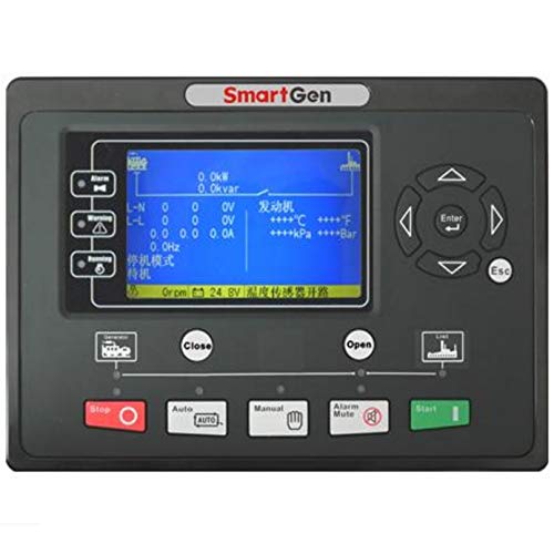
Imaxe: Unha fronte view of the HGM9310MPU Generator Controller with its LCD screen active, displaying operational data. Note: The text on the screen in this image is in Chinese, but the controller supports multiple languages including English.
Panel de control rematadoview:
- Pantalla LCD: Shows real-time operational data, alarms, and menu options.
- Botóns de navegación: Used to navigate through menus and adjust settings (Up, Down, Left, Right, Enter, Esc).
- Botón STOP: Stops the generator and resets alarms.
- Botón AUTO: Puts the controller in automatic mode, enabling automatic start/stop based on remote signals or mains status (for HGM9320MPU).
- Botón MANUAL: Allows manual control of the generator.
- ALARM MUTE Button: Silences audible alarms.
- Botón INICIO: Initiates manual start sequence for the generator.
Modos de operación básicos:
- Modo manual:
- Preme o MANUAL botón.
- Preme o INICIO button to manually start the generator.
- Preme o PARA button to manually stop the generator.
- Automatic Mode (HGM9310MPU):
- Preme o AUTO botón.
- The controller will monitor remote start signals. Upon receiving a valid signal, it will initiate the automatic start sequence.
- The generator will stop automatically when the remote start signal is removed.
- Automatic Mains Failure (AMF) Mode (HGM9320MPU only):
- Preme o AUTO botón.
- The controller continuously monitors the mains supply.
- If the mains supply fails, the controller will automatically start the generator and transfer the load.
- When mains power is restored, the controller will transfer the load back to the mains and shut down the generator after a cool-down period.
For detailed menu navigation, parameter setting, and advanced functions like scheduled start/stop or PLC programming, please consult the comprehensive user manual.
5. Mantemento
Regular maintenance ensures the longevity and reliable performance of your HGM9310MPU controller and the genset it manages. Always disconnect power before performing any maintenance.
General Maintenance Guidelines:
- Limpeza: Periodically clean the controller's display and panel with a soft, dry cloth. Avoid using abrasive cleaners or solvents that could damage the acrylic screen or silicon buttons.
- Comprobación de conexións: Regularly inspect all wiring connections for tightness and corrosion. Loose connections can lead to intermittent operation or faults.
- Actualizacións de firmware: Consulte o do fabricante website for any available firmware updates. Updates can improve performance, add features, or resolve known issues.
- Verificación de parámetros: Periodically verify that all configured parameters (e.g., voltage thresholds, delay timers) are still correct and meet operational requirements.
- Comprobación da batería: Asegúrese de que a batería do grupo electróxeno, que alimenta o controlador, estea en bo estado e debidamente cargada.
- Inspección ambiental: Ensure the controller's operating environment remains within specified temperature and humidity ranges. Check for any signs of moisture ingress or excessive dust accumulation.
- Event Log Review: Regularmente review the controller's event log for any recurring alarms or warnings. This can help identify potential issues before they become critical failures.
For specific maintenance schedules and procedures related to the genset itself, refer to the genset manufacturer's manual.
6 Solución de problemas
This section provides basic troubleshooting steps for common issues. For complex problems or persistent faults, contact technical support.
| Problema | Causa posible | Solución |
|---|---|---|
| A pantalla do controlador está en branco. | Sen subministración de enerxía; Cableado incorrecto; Fusible fundido. | Check DC power input (8-35V); Verify wiring connections; Check and replace fuses if necessary. |
| Generator fails to start in AUTO mode. | No remote start signal; Low battery voltage; Fuel level low; Engine fault. | Verify remote start signal; Check battery voltage; Ensure adequate fuel; Check engine for faults (e.g., oil pressure, temperature). |
| Indicación de alarma na pantalla. | Specific fault detected (e.g., over voltage, low oil pressure). | Note the alarm message; Refer to the full manual's alarm list for specific causes and remedies; Press ALARM MUTE to silence. |
| Incorrect readings (voltage, frecuencia, etc.). | Sensor malfunction; Incorrect parameter settings; Wiring issue. | Check sensor connections; Verify calibration parameters in controller settings; Inspect wiring for damage or loose connections. |
| Controller not communicating via USB/RS485. | Incorrect cable; Driver issues; Software settings; RS485 address conflict. | Ensure correct USB/RS485 cable; Install necessary drivers; Verify software communication settings; Check RS485 addresses. |
Always consult the detailed alarm list and troubleshooting guide in the complete user manual for comprehensive solutions.
7. Especificacións
Technical specifications for the HGM9310MPU Generator Controller.

Imaxe: A table outlining the detailed specifications of the HGM93XX MPU(CAN) series, including operating voltage, power consumption, alternator input range, frequency, speed sensor voltage/frequency, relay outputs, case dimensions, panel cutout, working conditions, storage conditions, protection level, insulating intensity, and net weight.
| Elemento | Contidos |
|---|---|
| Vol. Operativotage | DC8.0V to DC35.0V, Continuous Power Supply. |
| Consumo de enerxía | <4W (standby <2W) |
| <4W (standby <2W) | AC15V-AC 360V (ph-N) |
| 3-Fase 4-Filos | AC30V - AC620V (ph-ph) |
| 3-Fase 3-Filos | AC15V - AC360V (ph-N) |
| Single-Phase 2-Wire | AC15V - AC360V (ph-N) |
| 2-Fase 3-Filos | 50Hz/60Hz |
| Frecuencia do alternador | 1.0 V a 24.0 V (RMS) |
| Sensor de velocidade voltage | 10,000 Hz (máx.) |
| Frecuencia do sensor de velocidade | 16A DC28V supply output |
| Iniciar a saída de relé | 16A DC28V supply output |
| Saída de relé de combustible | 7A DC28V supply output |
| Auxiliary Relay Output (1) | 7A DC28V supply output |
| Auxiliary Relay Output (2) | 7A DC28V supply output |
| Auxiliary Relay Output (3) | 7A DC28V supply output |
| Auxiliary Relay Output (4) | 7A AC250V voltage saída libre |
| Auxiliary Relay Output (5) | 7A AC250V voltage saída libre |
| Auxiliary Relay Output (6) | 7A AC250V voltage saída libre |
| Dimensión do caso | 237 mm x 172 mm x 45 mm |
| Recorte do panel | 214 mm x 160 mm |
| C.T. Secondary | Clasificación 5A |
| Condicións de traballo | Temperatura: (-25~+70) °C; Humidade: (20~93) % HR |
| Condición de almacenamento | Temperatura: (-25~+70)°C |
| Nivel de protección | Junta IP55 |
| Intensidade illante | Aplicar CA 2.2 kV voltage entre alto voltage terminal e baixo voltage terminal; A corrente de fuga non supera os 3 mA en 1 min. |
| Peso neto | 0.85 kg |
8. Garantía e soporte
SMARTGEN products are manufactured to high quality standards. For warranty information and technical support, please refer to the official SMARTGEN websitio web ou póñase en contacto co seu distribuidor autorizado.
Información de contacto:
- For technical assistance, troubleshooting, or warranty claims, please contact SMARTGEN customer support.
- Refer to the contact details provided with your purchase or visit the official SMARTGEN websitio para obter a información de soporte máis actualizada.
Please have your product model number (HGM9310MPU) and purchase details ready when contacting support.


