1. Produto rematadoview
The ANENG Q1 is a 9999 counts True RMS digital multimeter designed for accurate measurement of various electrical parameters. It features an EBTN black screen with a large, backlit LCD for clear readability in diverse lighting conditions. This device supports both automatic and manual ranging, offering flexibility for different measurement needs. It includes an analog bar graph display for quick visual indication of readings.
Características principais:
- Medición de RMS verdadeiro: Proporciona lecturas precisas para formas de onda non sinusoidais.
- NCV (Non-Contact Voltage) Detección: For safe identification of live wires without direct contact.
- Rango automático/manual: User-selectable measurement range for convenience and precision.
- Gráfico de barras analóxico: Visual representation of measurement trends.
- Gran pantalla LCD retroiluminada: Visibilidade mellorada en contornas con pouca luz.
- Protección contra sobrecarga: Ensures safety across all measurement ranges.
- Indicación de batería baixa: Alertas cando é necesario substituír a batería.
- Función de retención de datos: Conxela a lectura visualizada para facilitar o rexistro.
- Apagado automático: Conserva a duración da batería.
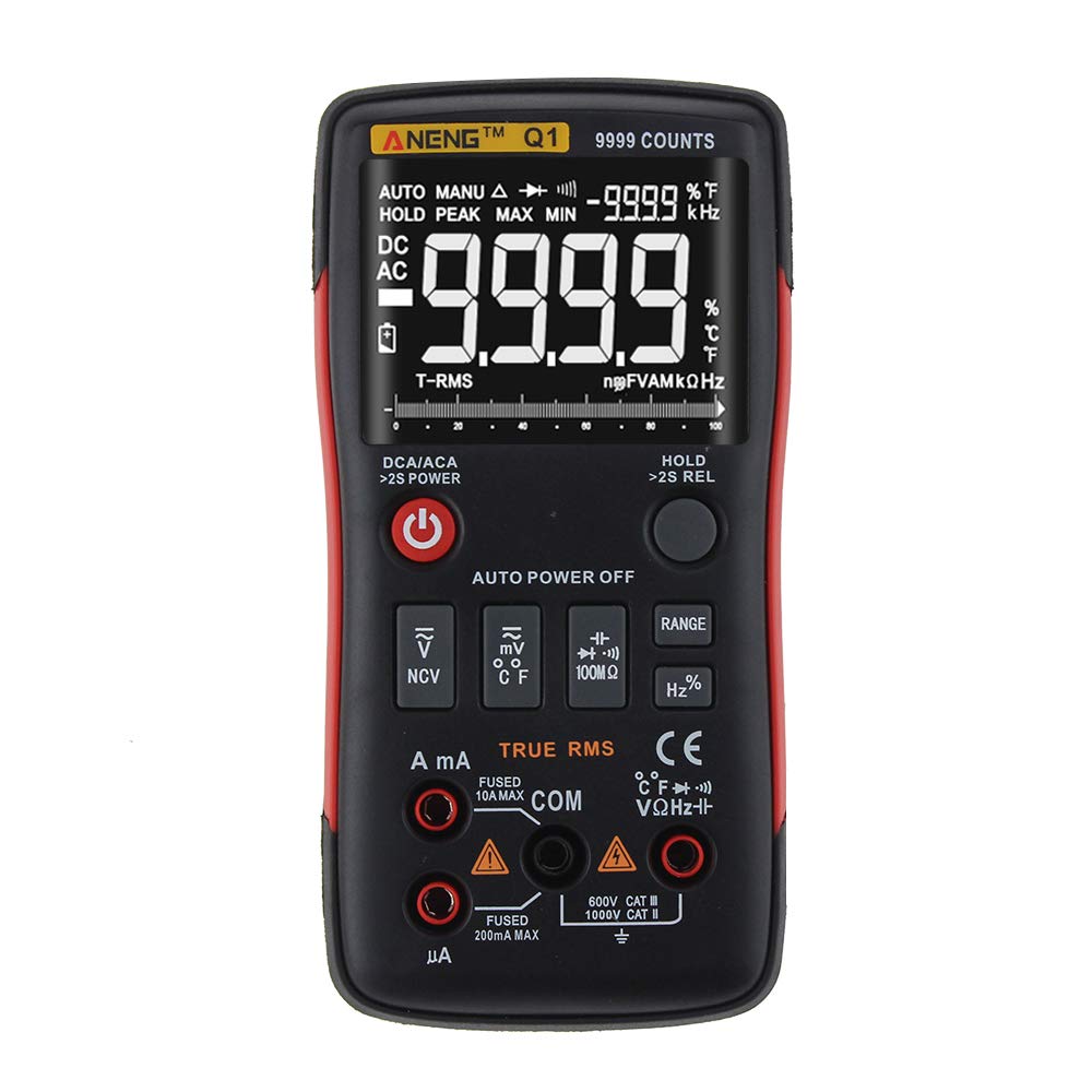
Figure 1: ANENG Q1 Digital Multimeter with its display and function buttons.
2. Información de seguridade
Always observe basic safety precautions when using this multimeter to prevent personal injury or damage to the device. Read and understand all safety information before operation.
- Non excedas os valores de entrada máximos para ningunha función.
- Teña coidado ao traballar con voltagpor riba de 30 V CA RMS, 42 V pico ou 60 V CC. Estes voltagsupoñen un perigo de descarga.
- Before measuring current, ensure the circuit is de-energized and the multimeter is connected in series.
- Desconecte sempre os cables de proba do circuíto antes de cambiar as funcións.
- Inspeccione os cables de proba para detectar danos no illamento ou metal exposto antes do uso. Substitúaos se están danados.
- Do not operate the multimeter if the battery cover is not properly closed.
- Substitúa as pilas inmediatamente cando apareza o indicador de pila baixa para garantir lecturas precisas.
- Cumprir os códigos de seguridade locais e nacionais.
3. Configuración
3.1 Instalación da batería
- Asegúrate de que o multímetro estea apagado.
- Localice o compartimento da batería na parte traseira do dispositivo.
- Desenrosque a tapa do compartimento da batería e retírea.
- Insert two 1.5V AA batteries, observing the correct polarity (+/-).
- Coloque a tapa da batería e fíxaa co parafuso.
3.2 Conexión dos cables de proba
The multimeter comes with a set of test leads. Always connect the black lead to the 'COM' (Common) jack. Connect the red lead to the appropriate input jack based on the measurement function:
- VΩHz+ jack for Voltage, Medicións de resistencia, frecuencia, capacitancia, díodo e continuidade.
- mA jack for current measurements up to 999.9mA.
- 10A jack for current measurements up to 10A.

Figure 2: Included test leads and probes.

Figure 3: Complete ANENG Q1 Multimeter kit with accessories.
4. Instrucións de funcionamento
The ANENG Q1 multimeter offers both automatic and manual ranging. Press the 'RANGE' button to switch between auto and manual modes. In manual mode, press 'RANGE' repeatedly to cycle through available ranges.
4.1 Encendido/apagado
Press the red power button to turn the multimeter on or off. The device features an auto power-off function to conserve battery life after a period of inactivity.
4.2 Medición AC/DC Voltage (V)
- Connect the black test lead to the 'COM' jack and the red test lead to the 'VΩHz+' jack.
- Seleccione o voltage measurement function (AC V or DC V) using the function button.
- Connect the test probes in parallel across the circuit or component to be measured.
- Le o voltago valor da pantalla.
4.3 Measuring AC/DC Current (A/mA/µA)
- Importante: Ensure the circuit is de-energized before connecting the multimeter for current measurement.
- Connect the black test lead to the 'COM' jack. Connect the red test lead to the 'mA' jack for currents up to 999.9mA, or to the '10A' jack for currents up to 10A.
- Select the current measurement function (AC A or DC A).
- Abra o circuíto e conecte o multímetro en serie coa carga.
- Volva a conectar a corrente ao circuíto e lea o valor da corrente na pantalla.
4.4 Medición da resistencia (Ω)
- Connect the black test lead to 'COM' and the red test lead to 'VΩHz+'.
- Select the resistance measurement function.
- Asegúrese de que o circuíto ou compoñente estea desconectado antes de medir a resistencia.
- Conecte as sondas de proba a través do compoñente.
- Lea o valor de resistencia na pantalla.
4.5 Medición da capacitancia (F)
- Connect the black test lead to 'COM' and the red test lead to 'VΩHz+'.
- Select the capacitance measurement function.
- Asegúrese de que o condensador estea completamente descargado antes de medir para evitar danar o multímetro.
- Conecte as sondas de proba aos terminais do condensador.
- Lea o valor da capacidade na pantalla.
4.6 Medición da frecuencia (Hz) e do ciclo de traballo (%)
- Connect the black test lead to 'COM' and the red test lead to 'VΩHz+'.
- Select the frequency/duty cycle measurement function.
- Connect the test probes across the signal source.
- Read the frequency or duty cycle value on the display.
4.7 Medición da temperatura (°C/°F)
- Connect the temperature probe to the appropriate input jacks (usually 'COM' and 'VΩHz+' or dedicated temperature jacks if available).
- Select the temperature measurement function.
- Coloque a punta da sonda de temperatura sobre ou preto do obxecto cuxa temperatura se vai medir.
- Lea o valor da temperatura na pantalla.
4.8 Proba de diodo
- Connect the black test lead to 'COM' and the red test lead to 'VΩHz+'.
- Select the diode test function.
- Conecta a sonda vermella ao ánodo e a sonda negra ao cátodo do díodo.
- A pantalla mostrará o volume de avancetagcaída de e. Inverta as sondas; un circuíto aberto (OL) indica un bo díodo.
4.9 Proba de continuidade
- Connect the black test lead to 'COM' and the red test lead to 'VΩHz+'.
- Seleccione a función de proba de continuidade.
- Conecte as sondas de proba a través do circuíto ou compoñente.
- Un pitido continuo indica unha traxectoria de baixa resistencia (continuidade).
4.10 NCV (Volumen sen contacto)tage) Detección
- Select the NCV function.
- Bring the top of the multimeter close to the conductor or outlet.
- O dispositivo indicará a presenza de CA voltage through an audible alarm and/or visual indicator.
5. Mantemento
5.1 Limpeza
Limpar o caso co anuncioamp un pano e un deterxente suave. Non empregue abrasivos nin disolventes. Asegúrese de que o dispositivo estea completamente seco antes de usalo.
5.2 Almacenamento
When not in use for extended periods, remove the batteries to prevent leakage. Store the multimeter in a cool, dry place, away from direct sunlight and extreme temperatures. The recommended storage conditions are -20°C to 60°C (-4°F to 140°F) with humidity less than 80% RH.
6 Solución de problemas
- Sen visualización: Comprobe a instalación das baterías e asegúrese de que non estean esgotadas. Substitúaas se é necesario.
- Lecturas incorrectas: Verify that the correct function and range are selected. Ensure test leads are properly connected and not damaged. Check battery level.
- Pantalla 'OL' (Sobrecarga): The measured value exceeds the selected range or the maximum input limit. Switch to a higher range or ensure the input is within the device's specifications.
- Sen pitido de continuidade: Check if the circuit is truly continuous and has very low resistance. Ensure test leads are making good contact.
7. Especificacións
7.1 Especificacións eléctricas

Figure 4: Electrical Specifications - DC and AC Voltage.

Figure 5: Electrical Specifications - DC and AC Current, and Resistance.

Figure 6: Electrical Specifications - Capacitance, Frequency, and Duty Cycle.

Figure 7: Electrical Specifications - Temperature, Diode, Continuity, and NCV.
7.2 General, Mechanical, and Environmental Specifications

Figure 8: General, Mechanical, and Environmental Specifications.
| Parámetro | Valor |
|---|---|
| Mostrar | LCD de 9999 contas |
| Variando | Automático/Manual |
| Material | ABS+TPE |
| Taxa de actualización | 3 veces/segundo |
| RMS verdadeiro | Si |
| Retención de datos | Si |
| Retroiluminación | Si |
| Indicación de batería baixa | Si |
| Apagado automático | Si |
| Parámetro | Valor |
|---|---|
| Dimensión | 146 * 74 * 34 mm |
| Peso | 125 g |
| Tipo de batería | 2 x 1.5V AA Battery (not included) |
| Parámetro | Valor |
|---|---|
| Temperatura de funcionamento | 0 ~ 40 °C |
| Humidade de funcionamento | <75% RH |
| Temperatura de almacenamento | -20~60°C |
| Humidade de almacenamento | <80% RH |
8. Garantía e soporte
8.1 Garantía
This ANENG Q1 Digital Multimeter comes with a garantía dun ano from the date of purchase, covering manufacturing defects. This warranty does not cover damage caused by misuse, accident, unauthorized modification, or normal wear and tear. Please retain your proof of purchase for warranty claims.
8.2 Atención ao cliente
For technical assistance, troubleshooting, or warranty inquiries, please contact the retailer or manufacturer's customer service. Refer to your purchase documentation for specific contact details.