1. Introdución
This manual provides detailed instructions for the safe and effective use of the IDEAL Electrical 61-327 600V Manual Range Multimeter. This device is designed for measuring AC/DC voltage, resistance, continuity, diodes, and testing batteries. It is a CAT III 600V rated instrument suitable for various electrical testing applications.

Figura 1.1: Fronte view of the IDEAL Electrical 61-327 Multimeter. This image displays the multimeter's main display, rotary dial, function buttons, and input jacks for test leads.
2. Información de seguridade
AVISO: To avoid electric shock or personal injury, read, understand, and follow all safety information and instructions before using this multimeter. Keep this manual for future reference.
- Always ensure the multimeter is in good working condition before use. Inspect test leads for damage.
- Non aplique máis que o voltage, como se marca no contador, entre os terminais ou entre calquera terminal e a terra.
- Teña coidado ao traballar con voltagpor riba de 30 V CA RMS, 42 V pico ou 60 V CC. Estes voltagsupoñen un perigo de descarga.
- Desconecte sempre a alimentación do circuíto e descargue todas as cargas de alto volumetage capacitores antes de probar resistencia, continuidade ou diodos.
- Do not operate the meter with the case open or the battery cover removed.
- Substitúa as pilas inmediatamente cando apareza o indicador de pila baixa para garantir lecturas precisas.
- This multimeter is rated for CAT III 600V. Do not use it in environments exceeding this rating.
3. Características do produto
The IDEAL Electrical 61-327 Multimeter offers a range of features designed for electrical professionals:
- UL Certified CAT III 600V: Ensures safety and reliability for AC/DC manual range measurements.
- Capacidades de medición: Medidas AC/DC voltage, resistance, continuity, diodes, and tests batteries.
- Vol. Sen contactotage (NCV) Sensing: Detecta AC voltage sen contacto directo, o que mellora a seguridade.
- Pantalla retroiluminada: Improves visibility in poorly lit environments.
- Built-in Probe Tip Holders: Allows for convenient and safer measurement by securing one lead.
- Hanging Strap Clip: Compatible with IDEAL hanging straps (sold separately, e.g., UMHS-757) for hands-free operation.
- Rugged Overmolding: Enhances grip and provides drop protection.
- Función de retención: Freezes the displayed reading for easier recording.
- Selectable Auto Power Off: Conserva a duración da batería.
4. Compoñentes e controis
Familiarize yourself with the main components and controls of your multimeter:

Figura 4.1: Fronte view of the multimeter, highlighting the display, rotary switch, and function buttons. The display shows measurement values and indicators. The rotary switch selects measurement functions. Buttons include HOLD and Backlight.

Figura 4.2: Included test leads and AAA batteries. The red and black test leads are essential for making electrical measurements. The batteries power the device.

Figura 4.3: Traseira view of the multimeter, showing the battery compartment cover and safety warnings. This view also illustrates the integrated test lead storage points.
5. Configuración
5.1 Instalación da batería
The multimeter requires three (3) 1.5V AAA batteries for operation. To install or replace batteries:
- Asegúrese de que o multímetro estea apagado.
- Locate the battery compartment on the back of the meter (refer to Figure 4.3).
- Usa un destornillador para afrouxar o parafuso que asegura a tapa da batería.
- Retire a tapa da batería.
- Insert three new 1.5V AAA batteries, observing the correct polarity (+/-) as indicated inside the compartment.
- Coloque a tapa da batería e aperte firmemente o parafuso.
5.2 Conexión dos cables de proba
Always connect the black test lead to the "COM" (Common) input jack. Connect the red test lead to the "VΩ" input jack for voltage, resistance, continuity, and diode measurements. Ensure connections are firm.
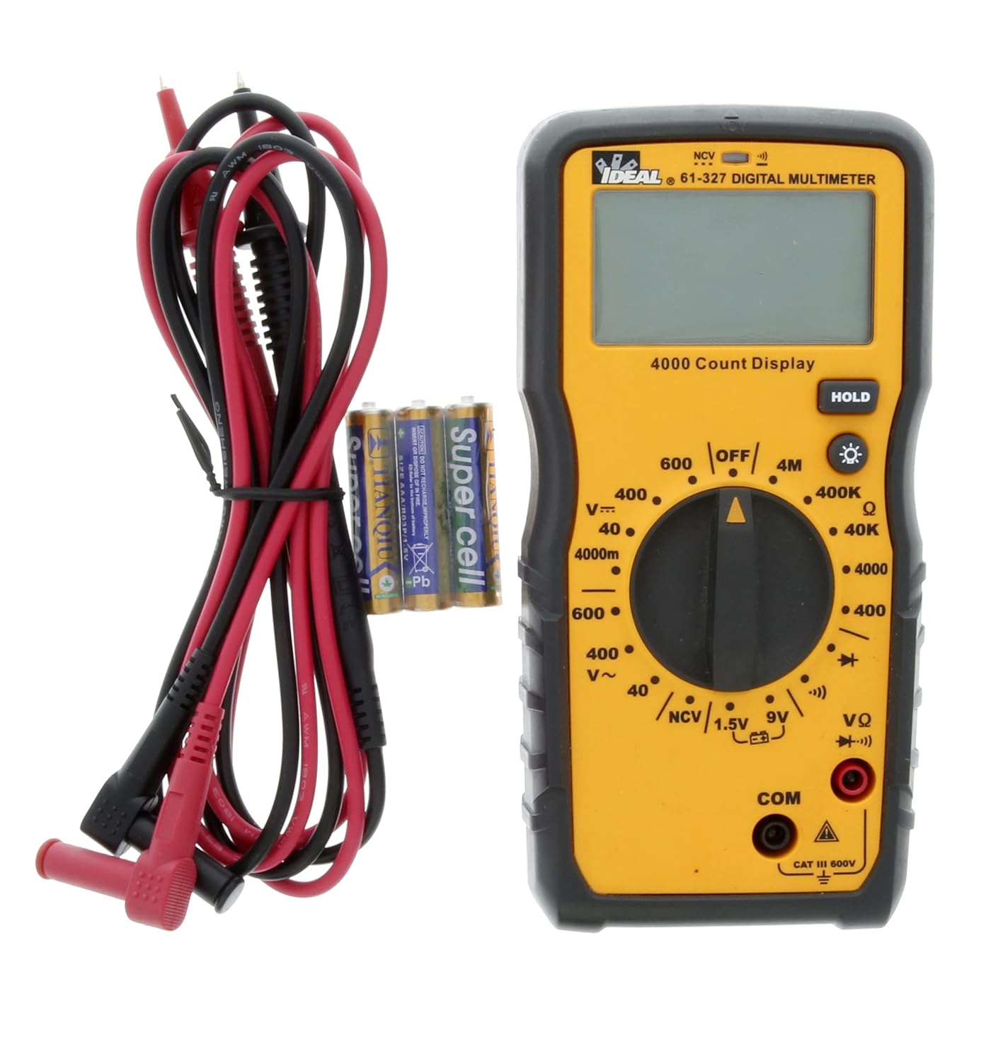
Figura 5.1: The multimeter shown with its test leads and batteries, ready for initial setup. The black lead connects to COM, and the red lead connects to VΩ.
6. Instrucións de funcionamento
This section details how to perform various measurements using the 61-327 Multimeter.
6.1 Medición AC/DC Voltage
- Xire o interruptor rotatorio ao volume de CA desexadotage (V~) ou Vol. CCtage (V=) range. Select a range higher than the expected voltage.
- Conecte o cable de proba negro á toma "COM" e o cable de proba vermello á toma "VΩ".
- Conecte as sondas de proba en paralelo ao circuíto ou compoñente que desexe medir.
- Le o voltago valor da pantalla.
6.2 Medición da resistencia (Ω)
- AVISO: Asegúrese de que o circuíto estea desenergizado e de que todos os condensadores estean descargados antes de medir a resistencia.
- Xire o interruptor rotatorio ao rango de resistencia (Ω) desexado.
- Conecte o cable de proba negro á toma "COM" e o cable de proba vermello á toma "VΩ".
- Connect the test probes across the component where resistance is to be measured.
- Lea o valor de resistencia na pantalla.
6.3 Proba de continuidade
- AVISO: Asegúrese de que o circuíto estea desenergizado antes de realizar unha proba de continuidade.
- Turn the rotary switch to the Continuity (•))) position.
- Conecte o cable de proba negro á toma "COM" e o cable de proba vermello á toma "VΩ".
- Toca as sondas de proba nos dous puntos nos que queres comprobar a continuidade.
- An audible tone indicates continuity (low resistance). The display will show the resistance value.
6.4 Proba de diodo
- AVISO: Ensure the circuit is de-energized before performing a diode test.
- Turn the rotary switch to the Diode (→|) position.
- Conecte o cable de proba negro á toma "COM" e o cable de proba vermello á toma "VΩ".
- Connect the red test probe to the anode and the black test probe to the cathode of the diode.
- A pantalla mostrará o volume de avancetage drop. Reverse the probes; the display should show "OL" (Open Loop) for a good diode.
6.5 Battery Test (1.5V / 9V)
- Turn the rotary switch to the 1.5V or 9V battery test position.
- Conecte o cable de proba negro á toma "COM" e o cable de proba vermello á toma "VΩ".
- Connect the red test probe to the positive terminal of the battery and the black test probe to the negative terminal.
- Ler a batería voltage na pantalla.
6.6 Vol. sen contactotage (NCV) Detección
A función NCV permite a detección do volume de CAtage without direct contact with conductors.
- Xire o interruptor rotativo á posición NCV.
- Move the top tip of the multimeter near the conductor or outlet to be tested.
- The meter will emit an audible tone and an illuminated red LED will flash when AC voltage is detected. The display may show "EF" or similar indication.

Figura 6.1: The multimeter being used to perform a Non-Contact Voltage (NCV) test near an electrical outlet. The display shows "EF" indicating voltage detección.
6.7 Uso da función HOLD
Prema o botón "HOLD" para conxelar a lectura actual na pantalla. Prémao de novo para soltar a retención e retomar as lecturas en directo.
6.8 Usando a luz de fondo
Press the backlight button (light bulb icon) to illuminate the display for better visibility in dark conditions. Press it again to turn off the backlight.
7. Mantemento
7.1 Limpeza
Limpar o contador con anunciosamp un pano e un deterxente suave. Non empregue abrasivos nin solventes. Asegúrese de que o medidor estea completamente seco antes de usalo.
7.2 Substitución da batería
Refer to Section 5.1 for instructions on battery installation and replacement. Always replace all three AAA batteries at the same time.
7.3 Inspección dos cables de proba
Regularly inspect test leads for any signs of damage, such as cuts, cracks, or frayed insulation. Replace damaged leads immediately to prevent electric shock.
8 Solución de problemas
| Problema | Causa posible | Solución |
|---|---|---|
| O medidor non se acende. | Baterías gastadas ou instaladas incorrectamente. | Check battery polarity; replace batteries (refer to Section 5.1). |
| Móstrase "OL" (sobrecarga). | A medición supera o rango seleccionado ou circuíto aberto. | Select a higher range or check for an open circuit in the component/wiring. |
| Lecturas inexactas. | Low battery, incorrect range selection, or damaged test leads. | Replace batteries, select appropriate range, inspect and replace test leads if damaged. |
| Sen ton de continuidade. | Circuíto aberto ou alta resistencia. | Verify the circuit is closed; check for breaks in wiring or components. |
9. Especificacións
Key technical specifications for the IDEAL Electrical 61-327 Multimeter:
- Número de modelo: 61-327
- Tipo de medida: Manual Range Digital Multimeter
- Clasificación de seguridade: UL certified CAT III 600V AC/DC
- Vol. ACtage: Ata 600V
- DC Voltage: Ata 600V
- Resistencia: Up to 4MΩ (4000kΩ)
- Continuidade: Audible tone and resistance display
- Proba de diodo: Si
- Proba de batería: 1.5 V, 9 V
- Vol. Sen contactotage (NCV): Si
- Visualización: Backlit, 4000 Count
- Fonte de enerxía: 3 pilas AAA de 1.5 V
- Apagado automático: Seleccionable
- Función de retención: Si
- Dimensións: Aproximadamente 9.09 x 6.18 x 3.35 polgadas
- Peso: Aproximadamente 1.1 libras
- Cor: Amarelo
- Fabricante: Ideal Industries

Figura 9.1: A comparison table of various IDEAL digital multimeters, including the 61-327, detailing their features and specifications. This table provides a quick overview of the 61-327's capabilities relative to other models.
10. Garantía e soporte
For warranty information, technical support, or service inquiries, please contact IDEAL Industries directly. Refer to the official IDEAL websitio web ou a embalaxe do produto para obter os datos de contacto máis actuais.
Additional resources, including a downloadable PDF user manual, may be available on the IDEAL Store on Amazon ou o oficial do fabricante websitio.


